Generation of a feedback signal for a polarization mode dispersion compensator in a communication system using alternate-polarization

a technology of polarization mode dispersion compensation and feedback signal, which is applied in the direction of electrical equipment, electrical transmission, transmission monitoring, etc., can solve the problems of complete receiver with clock and data recovery, severe degraded signal quality, and signal interference between subsequent symbols

Inactive Publication Date: 2015-02-17
RPX CORP
View PDF4 Cites 0 Cited by
  • Summary
  • Abstract
  • Description
  • Claims
  • Application Information

AI Technical Summary

Benefits of technology

[0016]The inventive method for generating a feedback signal avoids the need of a polarization scrambler: The feedback signal is based on two components and thus the feedback is typically not “blind” for particular launch polarization states as in case of a feedback signal based on measuring an RF-tone alone. Thus, a polarization scrambler is not mandatory anymore; nevertheless, a polarization scrambler may be still used (preferably, no polarization scrambler is used). The solution allows to reduce the costs when not using an additional polarization scrambler anymore. It should be noted that in case of using a polarization scrambler in case of RF-tone feedback typically one scrambler would be necessary per DWDM (dense wavelength division multiplex) channel since a single scrambler after a multiplexer for all DWDM channels may result in reliability problems. Moreover, any potential reliability problems associated with such polarization scrambler can be prevented when avoiding the scrambler.
[0019]For deriving the second signal, preferably a DLI with two output ports (a constructive output port and a destructive output port) and optical-to-electrical conversion means having two photodiodes are used. The first photodiode is coupled to the constructive output and the second photodiode is coupled to the destructive output. More preferably, a balanced photodetector is used for optical-to-electrical conversion. Evaluating both output ports of the DLI increases the swing of the second signal. Moreover, in case no remaining PMD is present, the measured intensity after a balanced photodetector and this also the second signal are essential zero (or very small). Thus, the adaption algorithm can be configured to minimize the feedback signal (comprising the second signal as a component), thereby minimizing the remaining PMD. It should be noted that also a single photodiode instead of two photodiodes may be used. In this case the single photodiode is typically connected to a single output port of the DLI.
[0020]Preferably, the first and second signals are both 0 or both minimal in case of no remaining PMD (i.e. in case of zero DGD). This allows to adapt the PMDC to the adaption target of zero DGD by minimizing both signals. Minimizing both signals may be realized by minimizing a preferred feedback signal formed by the sum of both signals.
[0023]According to a preferred embodiment of the method, the control loop minimizes the feedback signal when adapting the PMDC.

Problems solved by technology

With increasing channel transmission rate (in particular in case of 40 Gbps and beyond), PMD severely degrades the signal quality.
Therefore, the two portions separate along the fiber, thereby spreading the signal pulses and causing signal interference between subsequent symbols (also called ISI—intersymbol interference).
The latter two approaches have the drawback that they require a complete receiver with clock and data recovery; in the latter approach also an FEC unit is needed.
In case an extra receiver is dedicated to this purpose, the costs are increased.
Due to the alternate polarizations in APol modulation formats, the generation of a feedback signal for a PMDC in a transmission system using APol modulation is more difficult.
For Apol modulation, using DOP as feedback is not suitable since an Apol signal is inherently depolarized.
Generating a feedback signal by monitoring the intensity of a radio-frequency (RF) spectral line is also problematic in case of Apol modulation.

Method used


Image

  • Generation of a feedback signal for a polarization mode dispersion compensator in a communication system using alternate-polarization
  • Generation of a feedback signal for a polarization mode dispersion compensator in a communication system using alternate-polarization
  • Generation of a feedback signal for a polarization mode dispersion compensator in a communication system using alternate-polarization

Examples


Embodiment Construction

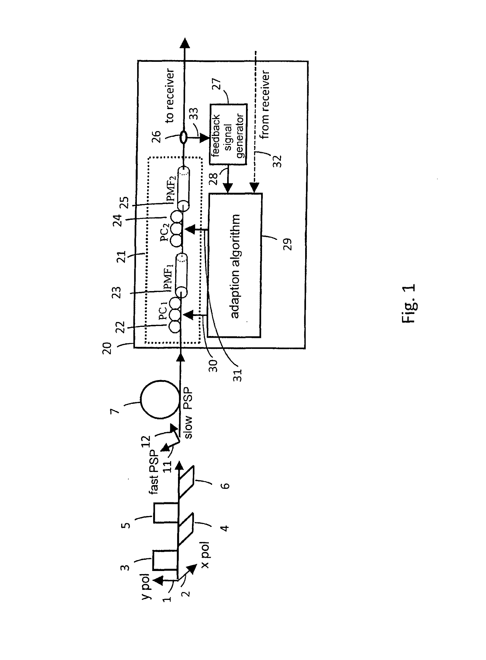
[0053]FIG. 1 shows a feedback loop for adapting a PMDC in a transmission system using an Apol format. Such transmission system preferably uses a 40 or 43 Gbps Apol RZ DPSK format. Preferably, the transmission system is a long-haul transmission system, in particular a submarine transmission system. The right hand of FIG. 1 illustrates an example for an Apol RZ signal as generated by a transmitter. The Apol signal has a plurality of RZ pulses 3-6, where each pulse 3-6 has either a first polarization 1 (here: “x pol”) or a second polarization 2 (here: “y pol”). Both polarizations 1, 2 are orthogonal to each other. As shown in FIG. 1, two consecutive pulses 3-6 are transmitted in different polarizations 1, 2, e.g. in the TE (transverse electric) polarization and the TM (transverse magnetic) polarization. Each pulse 3-6 is preferably phase modulated. In case of Apol RZ PSK and Apol RZ DPSK, each pulse has one of two possible phase states, e.g. 0 or π. The stream of pulses 3-6 can be subd...


PUM


Abstract

The invention relates to a method of generating a feedback signal for adjusting a polarization mode dispersion compensator (PMDC, 21) in a transmission system with alternate-polarization. A first signal (37) is determined by measuring a spectral component of the radio frequency modulation of an optical signal (33) at a particular radio frequency. Preferably, the radio frequency essentially corresponds to half the symbol rate of the optical signal (33). Also a second signal (35) is determined by coupling the optical signal (33) into a delay line interferometer (DLI, 50) having a delay essentially corresponding to the symbol period or an odd multiple of the symbol period between its arms (51, 54). Downstream of the DLI (50), the signal is optical-to-electrically converted. Downstream of the optical-to-electrical conversion, an intensity measurement is performed. The first (37) and second (35) signals are then combined to generate the feedback signal (28).

Description

FIELD OF THE INVENTION[0001]The invention relates to compensation of polarization mode dispersion (PMD) in optical communication systems, in particular to the generation of a feedback signal for adjusting a polarization mode dispersion compensator (PMDC) in a communication system using an alternate-polarization (Apol) format.BACKGROUND OF THE INVENTION[0002]With increasing channel transmission rate (in particular in case of 40 Gbps and beyond), PMD severely degrades the signal quality. The reason for PMD is that an optical fiber exhibits two orthogonal principle axes corresponding to two principle states of polarization (PSP), which have different travelling speeds. A signal's first portion aligned with one principle axis propagates with different speed than a signal's second portion aligned with the other principle axis. Therefore, the two portions separate along the fiber, thereby spreading the signal pulses and causing signal interference between subsequent symbols (also called I...

Claims


Application Information

Patent Timeline
Patent Type & Authority Patents(United States)
IPC IPC(8): H04B10/00H04B10/079H04B10/2569H04B10/532
CPCH04B10/07951H04B10/2569H04B10/532
Inventor KLEKAMP, AXELBULOW, HENNING
Owner RPX CORP
Why Eureka
Try Eureka