Drill and drilling method for workpiece

a drilling method and workpiece technology, applied in the direction of twist drills, manufacturing tools, wood boring tools, etc., can solve the problems of reducing the wear resistance of the drill bit, the cutting edge wear resistance of the double angle drill bit is not high, and the drill bit wear resistance is low. to achieve the effect of high precision drilling and increased cutting edge wear resistan

Active Publication Date: 2015-11-10
SUBARU CORP
View PDF51 Cites 3 Cited by
  • Summary
  • Abstract
  • Description
  • Claims
  • Application Information

AI Technical Summary

Benefits of technology

[0013]The present invention is made to address the above-mentioned problems of the related art, and an object of the present invention is, in a drill including a cutting edge a point angle of which varies depending on a position, to increase wear resistance of the cutting edge. Accordingly, high precision drilling for a long term can be provided.
[0014]Also, another object of the present invention is, when a metal material and a fiber reinforced plastic composite material are drilled, to prevent delamination and fiber fraying from appearing at the fiber reinforced plastic composite material.
[0016]With the aspect, since the cutting edge has the point angle which is decreased from the center position to the maximum diameter position in a continuous changing manner, the ridgeline has no corner, which is likely chipped. Also, a cutting load is decreased at a position near the maximum diameter, thereby increasing wear resistance of the cutting edge.
[0017]In addition, with the aspect, since the cutting edge has the relief angle which is decreased in a continuous changing manner, a relief face has no corner, which is likely subjected to wear. Also, reaming is performed at a position near the maximum diameter, thereby increasing the wear resistance of the cutting edge.
[0018]Further, with the aspect, since the ridgeline of the cutting edge is formed of a curve (including a case in which a straight line is partly contained), a cutter section of this aspect has a longer edge length as compared with a cutter section with an equivalent size of a conventional cutting edge having a ridgeline formed of a straight line. With the large edge length, regarding a certain cutting amount, a cutting amount per unit length of the ridgeline of the cutting edge is decreased, and hence a wear amount is decreased, thereby increasing the wear resistance of the cutting edge.
[0019]Accordingly, with the aspect, by increasing the wear resistance of the cutting edge as described above, high precision drilling for a long term can be provided.

Problems solved by technology

Unfortunately, as disclosed in document '612, the double angle drill typically has low wear resistance.
Thus, such a shape of the drill decreases the wear resistance of the drill.
In addition, to drill a hole in a component member, as a workpiece, in which a metal material and a fiber reinforced plastic composite material are combined, the double angle drill still has problems as follows.
In a situation in which the component member is drilled by the double angle drill from the metal material side, when the fiber reinforced plastic composite material is drilled after the metal material is drilled, the primary cutting edge penetrates through the fiber reinforced plastic composite material while insufficiently cutting but pressing fibers of the fiber reinforced plastic composite material.

Method used


Image

  • Drill and drilling method for workpiece
  • Drill and drilling method for workpiece
  • Drill and drilling method for workpiece

Examples


first embodiment

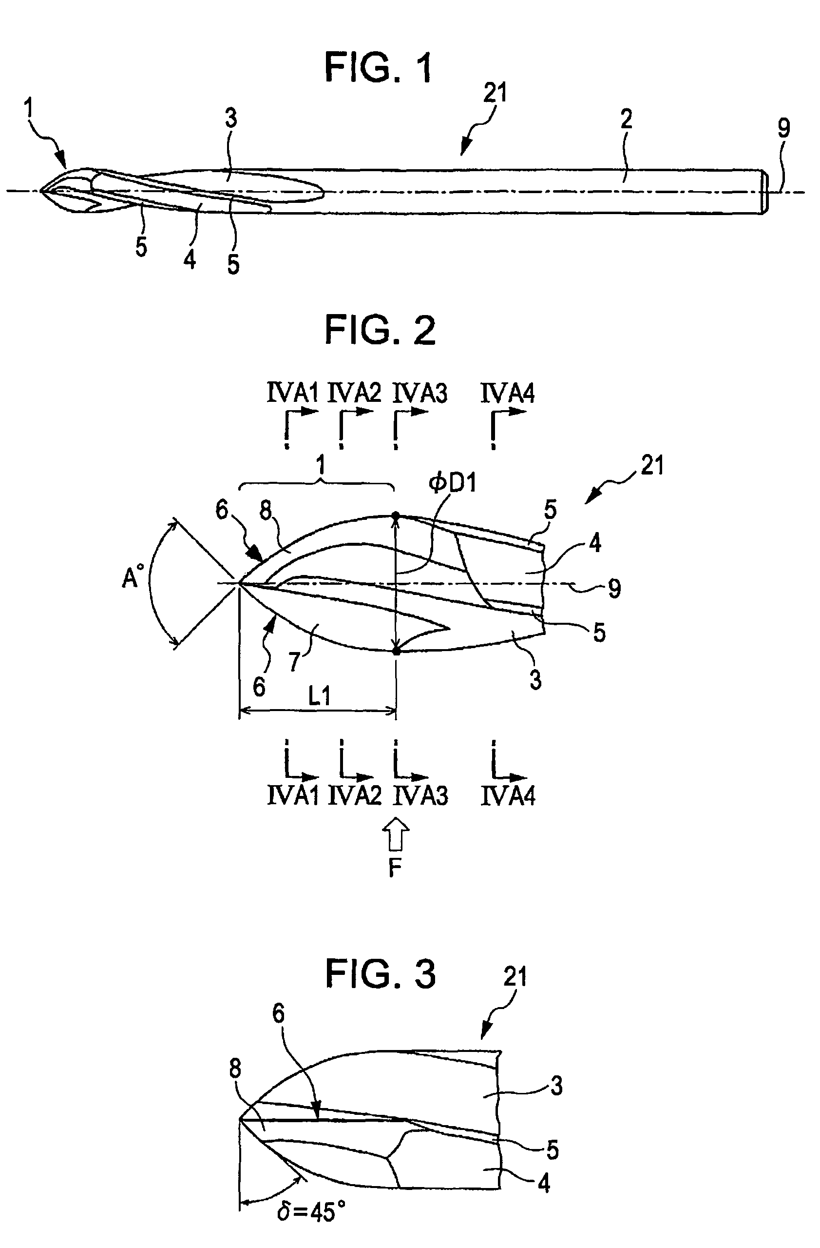
[0047]A first embodiment of the present invention is described below with reference to FIGS. 1 to 4B4. FIG. 1 is a side view showing a drill according to the first embodiment of the present invention.

[0048]Referring to FIG. 1, a drill 21 of this embodiment includes a cutter section 1 and a shank section 2. Helical flutes 3 are formed on the cutter section 1 and the shank section 2.

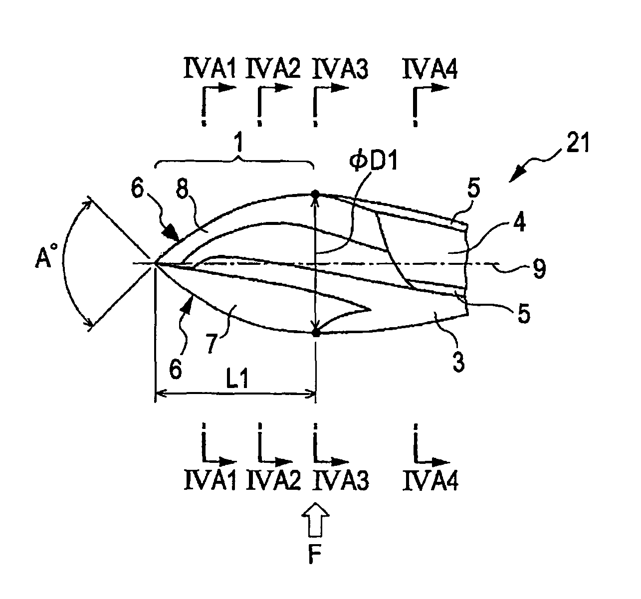
[0049]FIG. 2 is an enlarged view showing a tip portion of the drill 21 in FIG. 1.

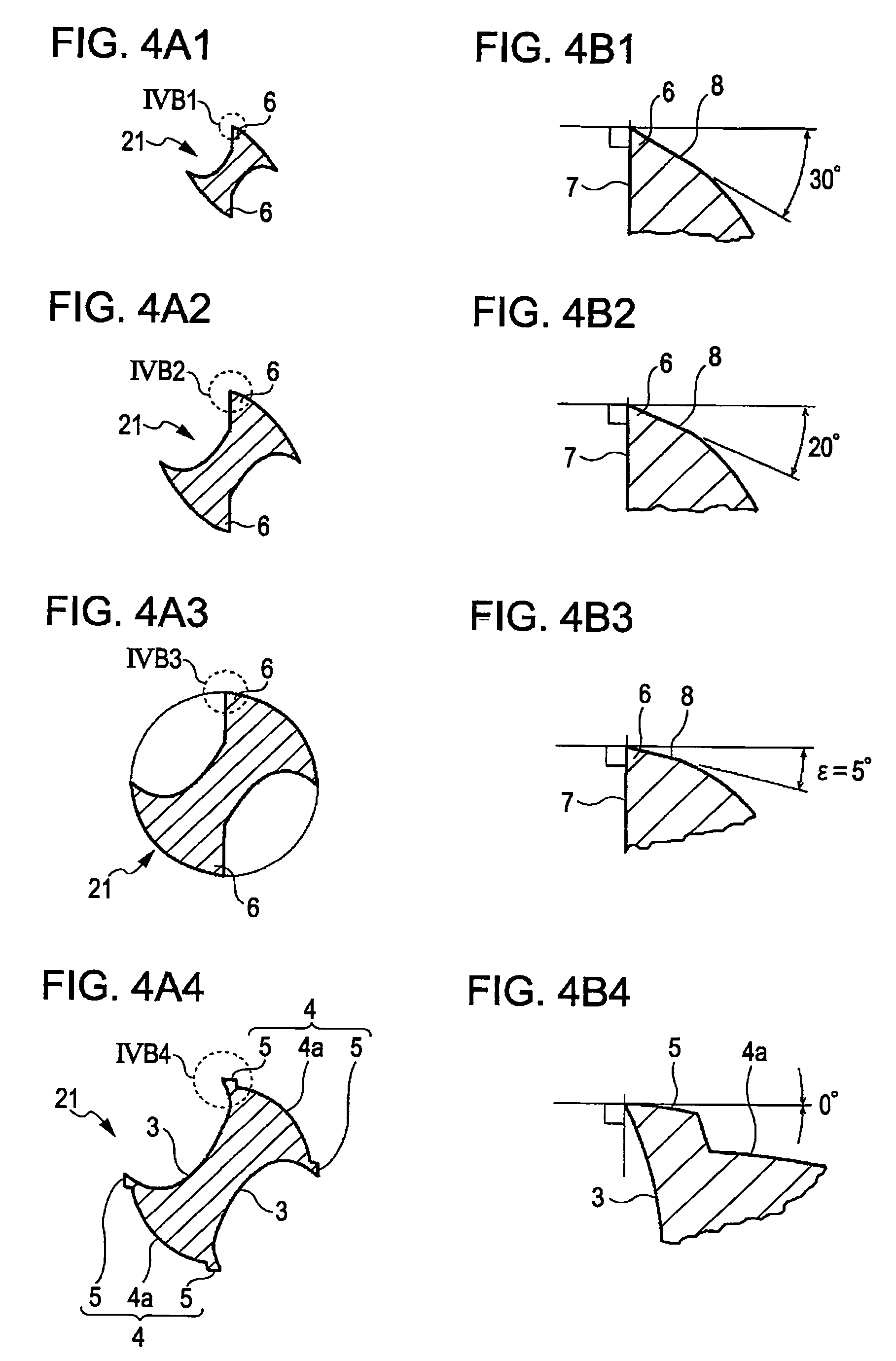
[0050]The cutter section 1 includes a pair of cutting edges 6 arranged symmetrically about an axis 9. The cutting edges 6 each have a rake face 7 and a relief face 8.

[0051]The cutter section 1 is finished by X thinning (cross thinning), and rake faces 7 are formed at portions removed by thinning. The portions removed by thinning are continuous to the helical flutes 3. The helical flutes 3 are two threads which are twisted at a predetermined helix angle. Lands 4 are formed between the helical flutes 3. Margins 5 are formed at e...

second embodiment

[0068]Next, a second embodiment of the present invention is described. FIGS. 7A1 to 7B4 are cross-sectional views each showing a drill according to the second embodiment of the present invention. The positional relationship of the cross sections is similar to that of FIGS. 2A1 to 2B4. A drill 22 of this embodiment includes a cutting edge having a rake angle and is suitable for metal processing.

[0069]Referring to FIGS. 7A1 to 7A3, and 7B1 to 7B3, a cutting edge 6a has a rake angle. In particular, the cutting edge 6a has a rake face 7a inclined toward a relief face 8 with respect to a line 10 orthogonal to a work surface. Other structure is similar to that of the drill 21 of the first embodiment. Dimensions of respective parts are designed depending on the purpose of use.

[0070]When the drill 22 is applied to metal processing, for example, referring to FIG. 8, the slenderness ratio (L1 / φD1) of a cutter section 1 is set smaller than that for a composite material. In this case, the ridge...

third embodiment

[0071]Next, a third embodiment of the present invention is described. FIG. 9 is a cross-sectional view showing a drill according to the third embodiment of the present invention. FIG. 10 is a cross-sectional view taken along line X-X in FIG. 9. A drill 23 of this embodiment is configured such that the helical flutes 3 of the drill 21 in the above-described first embodiment are replaced by V-grooves 11.

[0072]Referring to FIG. 9, the drill 23 includes a cutter section 1b and a shank section 2. The cutter section 1b includes a pair of cutting edges 6b arranged symmetrically about an axis 9. The cutting edges 6b each have a rake face 7b and a relief face 8b. Referring to FIGS. 9 and 10, two V-grooves 11 are formed between the cutter section 1b and the shank section 2. The V-grooves 11, including a removed portion of the cutter section 1b by thinning, are formed straight along the axis 9.

[0073]Referring to FIG. 10, lands 12 are formed between the V-grooves 11, and margins 13 are formed a...


PUM

PropertyMeasurementUnit
point angleaaaaaaaaaa
angleaaaaaaaaaa
relief angleaaaaaaaaaa

Abstract

A drill includes a cutting edge. The cutting edge has a point angle which is continuously decreased from a center-position point angle A (herein, 0°<A<180°) at a center position to a maximum-diameter-position point angle of 0° at a maximum diameter position. The cutting edge has a relief angle which is continuously decreased from the center position to the maximum diameter position. The cutting edge of the drill has a relief angle at the maximum diameter position. Hence, the cutting edge also serves as a cutting edge for reaming. The ridgeline and relief face of the cutting edge have no corner, thereby providing good wear resistance.

Description

BACKGROUND OF THE INVENTION[0001]1. Field of the Invention[0002]The present invention relates to a drill including a cutting edge a point angle of which varies depending on a position, and a drilling method for a workpiece.[0003]2. Description of the Related Art[0004]Examples of the drill including the cutting edge a point angle of which varies depending on a position may be double angle drills disclosed in Japanese Unexamined Patent Application Publication No. 63-306812 (hereinafter, referred to as document '812) and in Japanese Unexamined Utility Model Application Publication No. 06-75612 (hereinafter, referred to as document '612).[0005]Such a double angle drill includes a primary cutting edge and a secondary cutting edge. The tip portion of the primary cutting edge has a tip shape of a metal drill. The secondary cutting edge is flat, is continuous to the primary cutting edge, and has a smaller point angle than that of the primary cutting edge.[0006]Documents '812 and '612 teach ...

Claims


Application Information

Patent Timeline
Patent Type & Authority Patents(United States)
IPC IPC(8): B23B51/02B23B35/00
CPCB23B51/02B23B35/005B23B35/00B23B2222/56B23B2226/275B23B2251/04B23B2251/082B23B2251/14B23B2251/18Y10T408/03Y10T408/9097B23B2226/61B23B2228/36
Inventor NAKAHATA, TATSUOSAITO, MANABUHOSOI, MASANORITAKAHASHI, HIDEHARU
Owner SUBARU CORP
Why Eureka
Try Eureka