Work apparatus having a fuel pump

a fuel pump and work apparatus technology, applied in the direction of fuel injection apparatus, machine/engine, feed system, etc., can solve the problems of vapor bubble formation and the inability of the fuel pump to deliver any more fuel, and achieve the effect of simple design, reduced number of required components, and simplified assembly

Active Publication Date: 2015-11-10
ANDREAS STIHL AG & CO KG
View PDF22 Cites 2 Cited by
  • Summary
  • Abstract
  • Description
  • Claims
  • Application Information

AI Technical Summary

Benefits of technology

[0007]The component is advantageously arranged at least partially in a depression of the fuel tank. The arrangement of the component at least partially in a depression of the fuel tank ensures that there is only a small height difference between the delivery pump and the fuel level in the case of a customary parked position of the work apparatus. As a result, the hydrostatic pressure difference which is to be overcome between the fuel, tank and the delivery pump and is a result of the different height position is comparatively low in the case of the arrangement of the component in a depression of the fuel tank. The hydrostatic pressure level between the delivery pump and the fuel tank also differs only a little. As a result, the power output which is required to drive the fuel pump and the force which is to be applied by the operator in order to actuate the delivery pump can be kept low.
[0016]The tank wall advantageously has a connection opening adjacently to the component. An intake line which connects the tank interior to the fuel pump is advantageously integrated into the component. The fuel pump can foe connected to the tank interior in a simple way via the connection opening and the intake line. This results in a simple construction. An intake line which is configured as a separate hose can be dispensed with. The assembly is simplified, since the intake line does not have to be connected. During the mounting of the component on the fuel tank, the integrated intake line is connected to the connection opening. The seal can be effected in a simple way between the pump housing of the component and the tank wall.

Problems solved by technology

If the fuel pump is heated excessively during the operation of the internal combustion engine and, in particular, also after the internal combustion engine is switched off, when no more cooling air is delivered and the internal combustion engine is still hot, vapor bubbles can be formed.
If there are vapor bubbles in the fuel pump, the fuel pump cannot deliver any more fuel, in particular when it is configured as a diaphragm pump.

Method used


Image

  • Work apparatus having a fuel pump
  • Work apparatus having a fuel pump
  • Work apparatus having a fuel pump

Examples


Embodiment Construction

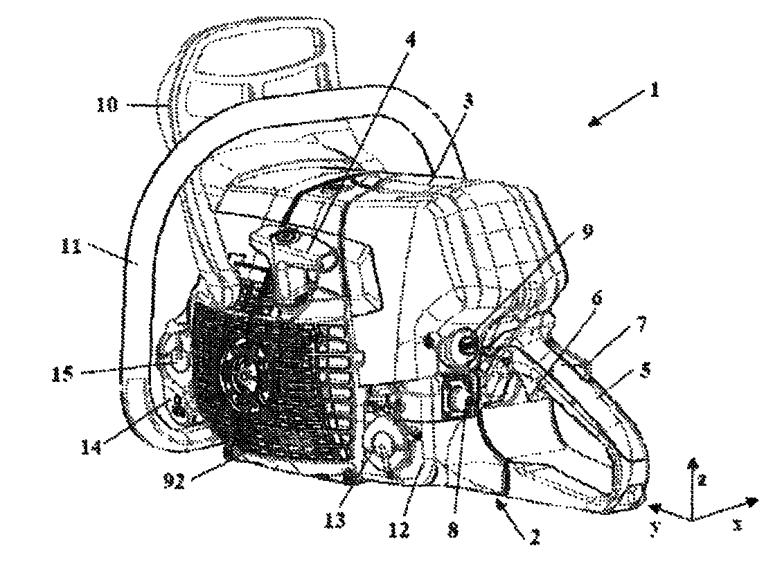
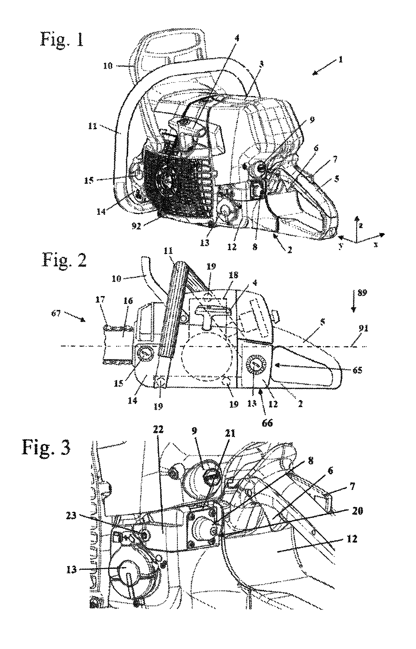
[0028]As an exemplary embodiment for a work apparatus, FIG. 1 shows a hand-held motor-driven chain saw 1. Instead of the chain saw 1, another hand-held work apparatus can be provided, such as a cutoff machine, a brushcutter or the like. The chain saw 1 has a handle housing 2 and an engine housing 92. A rear handle 5 is formed on the handle housing 2, on which rear handle 5 a hand throttle 6 and a hand throttle lock 7 are pivotably mounted. Moreover, a fuel tank 12 is formed on the handle housing 2, which fuel tank 12 is closed by a tank cap 13.

[0029]As FIG. 2 shows, the handle housing 2 is decoupled in terms of vibration from the engine housing 92 via three anti-vibration elements 19. In addition, further anti-vibration elements can be provided. An internal combustion engine 18 is arranged in the engine housing 92. The starting handle 4 which is shown in FIGS. 1 and 2 serves to start the internal combustion engine 18. The internal combustion engine 18 is covered by the hood 3 which ...


PUM


Abstract

A work apparatus has an internal combustion engine for driving a work tool of the work apparatus and a fuel pump which is driven by the engine and delivers fuel from a fuel tank to the engine. The work apparatus has a feed pump which is to be actuated manually by the operator. The fuel pump and the feed pump form one assembly which is arranged outside the fuel tank. The fuel tank has a tank wall which delimits the tank interior. An advantageous arrangement and satisfactory cooling of the assembly are achieved if the assembly is arranged at least partially on the tank wall.

Description

CROSS REFERENCE TO RELATED APPLICATION[0001]This application claims priority of German patent application no. 10 2012 007 617.7, filed Apr. 18, 2012, the entire content of which is incorporated herein by reference.BACKGROUND OF THE INVENTION[0002]U.S. Pat. No. 6,595,500 discloses a hand-held work apparatus having a diaphragm carburetor. A fuel pump, which is driven by the varying crankcase pressure, and a delivery pump, which is to foe actuated manually, are integrated into the diaphragm carburetor. Carburetors of this type are usually arranged on the internal combustion engine or directly adjacently to the internal combustion engine.[0003]For example, U.S. Pat. No. 4,286,553 also discloses feeding the fuel to an internal combustion engine via an injection valve. The fuel is delivered by a fuel pump to the injection valve.SUMMARY OF THE INVENTION[0004]It is an object of the invention to provide a work apparatus having an advantageous arrangement of an assembly or a component compris...

Claims


Application Information

Patent Timeline
Patent Type & Authority Patents(United States)
IPC IPC(8): F02M55/02F02M1/16F02B63/02F02M37/00F02M37/04F02M37/16F02M37/18
CPCF02B63/02F02M1/16F02M37/007F02M37/0011F02M37/046F02M37/16F02M37/18
Inventor LANK, JONASZIMMERMANN, HELMUTUHL, KLAUS-MARTIN
Owner ANDREAS STIHL AG & CO KG
Why Eureka
Try Eureka