Bearing adjuster

a technology of bearings and adjusters, applied in the field of bearing adjusters, can solve the problems of inconvenient use, imbalanced bearing installation, shortcoming of pounding force applied inconsistently, etc., and achieve the effect of convenient us

Active Publication Date: 2015-11-17
HUNG CHENG HAO
View PDF9 Cites 5 Cited by
  • Summary
  • Abstract
  • Description
  • Claims
  • Application Information

AI Technical Summary

Benefits of technology

[0005]A primary objective of the present invention is to provide a bearing adjuster able to adjust its' diameter to coordinate with bearings in different sizes so that the pounding force can be consistently distributed to the bearings when the bearings are installed. Therefore, the bearing adjuster is very stable and convenient in use.
[0011]Preferably, a washer is disposed on the threaded rod of the grip in order to help the grip to join with the fixing member more securely so as to prevent falling-off. The grip is bored with anti-slip pattern thereon, which can make it convenient for the user to hold the grip without falling-off. Two opposite planes are formed on the grip and can be clamped by an auxiliary tool. In addition, anti-slip pattern is provided around circumference of adjusting member, which can make it convenient for the user to grab the adjusting member without falling-off.

Problems solved by technology

However, the conventional way of installing the bearing has the shortcoming which the pounding force is applied inconsistently.
That is all because the hammer pounds the bearing at different portions for multiple numbers of times and subjected to different pounding forces which will cause the imbalance installation of the bearing.
This is much inconvenient in use.
Moreover, if the aforesaid bearing adjuster set is used to install many bearings in different sizes, it is particularly inconvenient to prepare the necessary tools and replace the positioning press blocks 72 with different diameters.

Method used


Image

  • Bearing adjuster
  • Bearing adjuster
  • Bearing adjuster

Examples


Embodiment Construction

[0021]Herein below, the technical means adopted by the present invention to achieve the aforesaid objective and efficacy will be detailed as follows with reference to preferred feasible embodiments and the attached drawings.

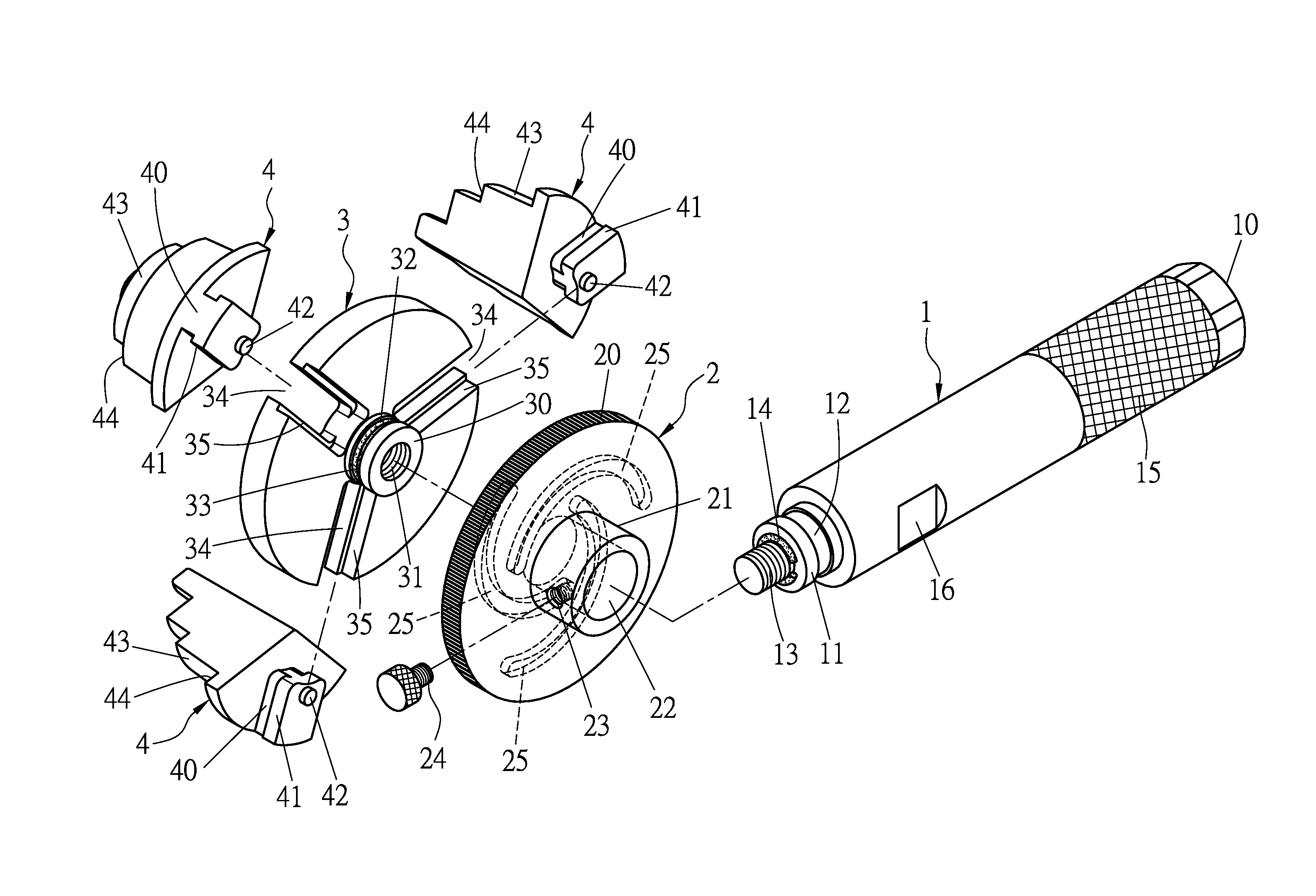
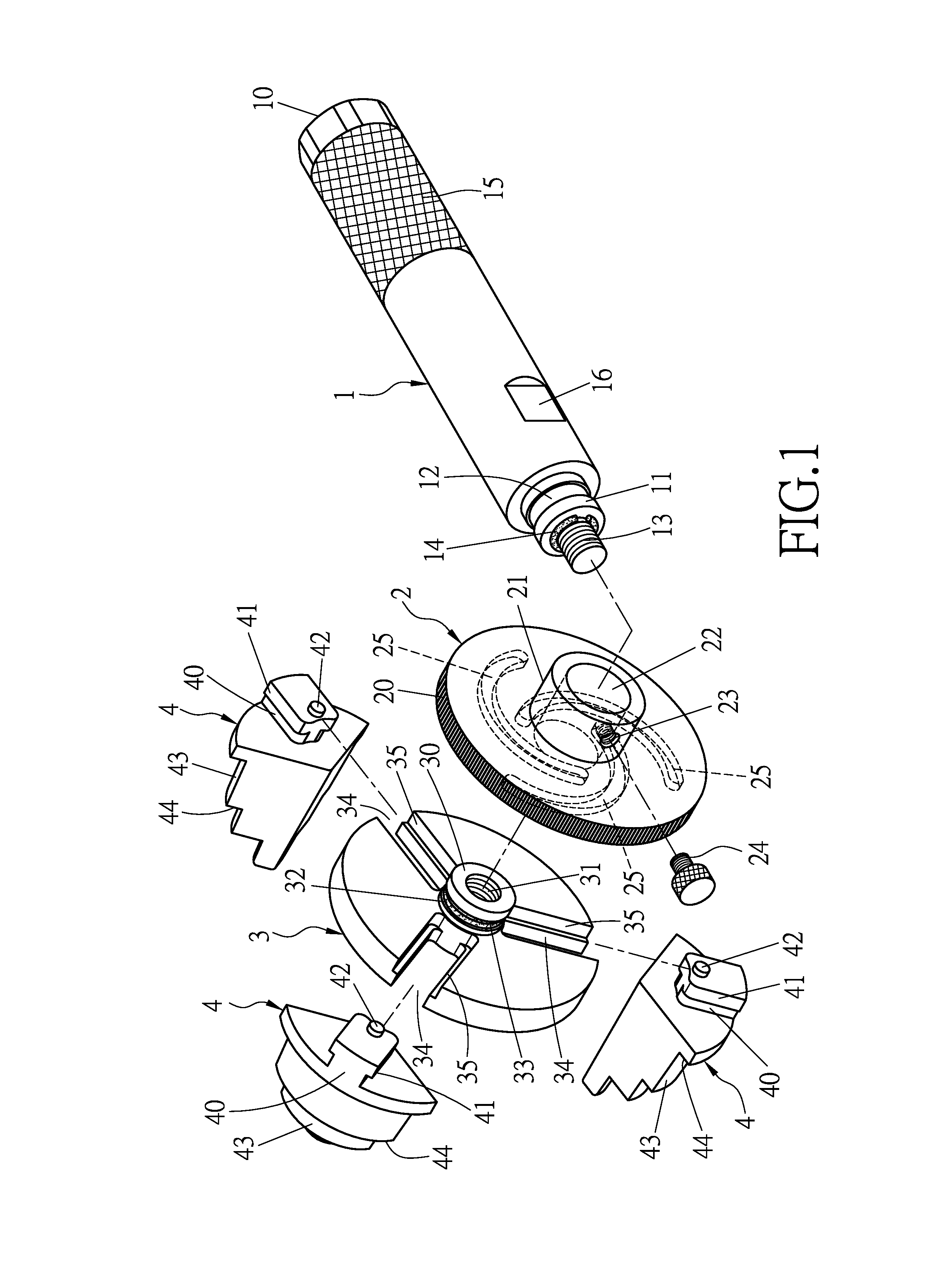
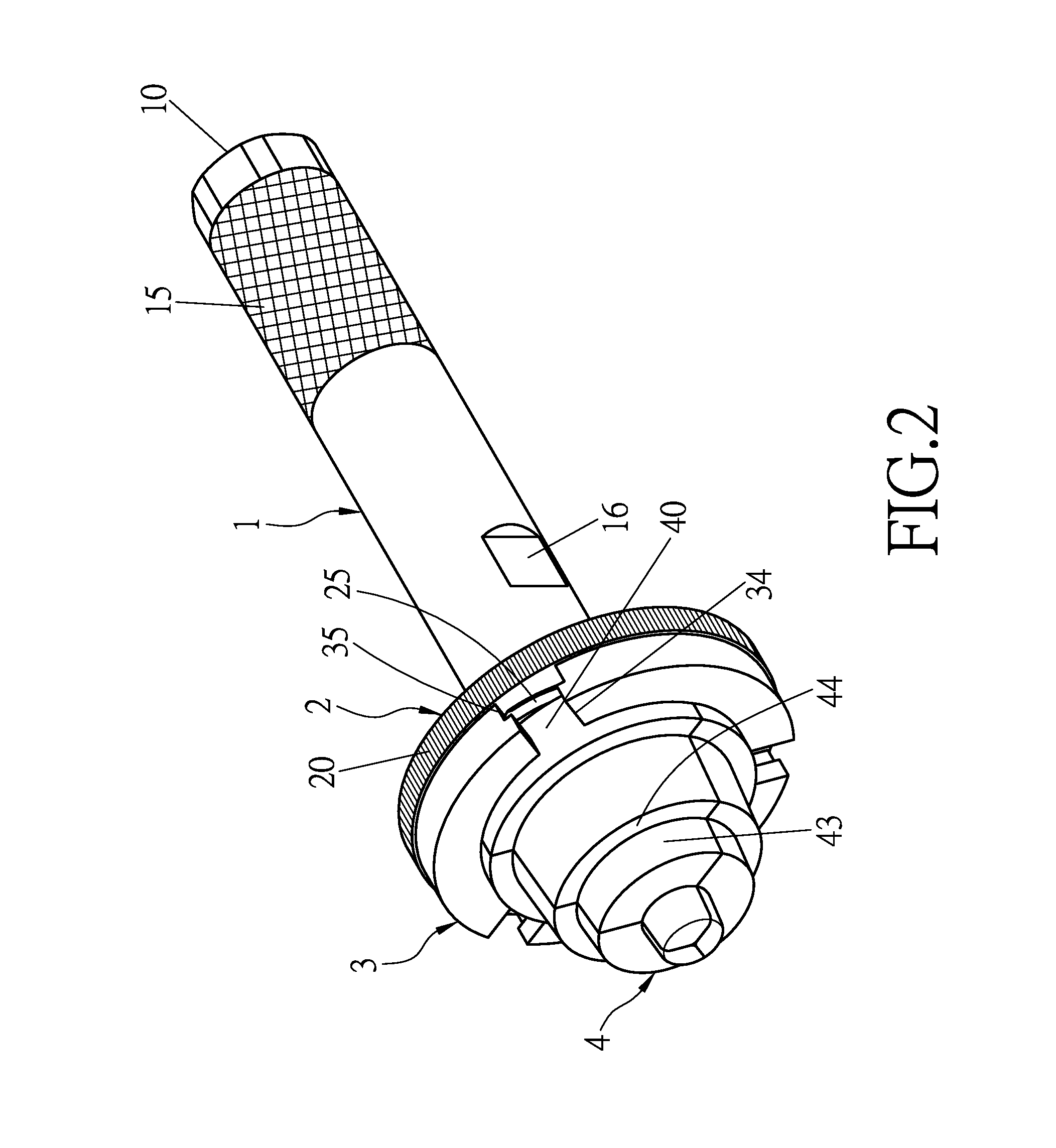
[0022]Referring to FIG. 1-4, an embodiment of the present invention mainly includes a grip 1, an adjusting member 2, a fixing member 3, and three movable members 4.

[0023]The grip 1 having an end provided with a pounding portion 10 and the other end provided with a protrusion 11, wherein a positioning annular groove 12 is formed around the protrusion 11, a threaded rod 13 is disposed in front of the protrusion 11, a washer 14 is disposed on the threaded rod 13, and the grip 1 is formed with anti-slip pattern 15 thereon and formed with two opposite planes 16.

[0024]The adjusting member 2 disposed on the protrusion 11 of the grip 1, wherein anti-slip pattern 20 is formed around circumference of the adjusting member 2, a connecting protrusion 21 is disposed on a side ...


PUM

PropertyMeasurementUnit
circumferenceaaaaaaaaaa
diameteraaaaaaaaaa
sizesaaaaaaaaaa

Abstract

A bearing adjuster is comprised of a grip, an adjusting member, a fixing member and three movable members. The adjusting member is disposed on a protrusion of the grip. The fixing member is disposed on the adjusting member. The movable members are disposed on the fixing member correspondingly. A threaded rod of the grip is screwed in a threaded hole of a positioning protrusion of the fixing member. A sliding block of each movable member and positioning guide blocks of the sliding block are disposed in one of sliding grooves of the fixing member and positioning guide grooves of the sliding groove respectively. A guide protrusion of the movable member is disposed in one of corresponding grooves of the adjusting member. Thus, the bearing adjuster is able to adjust its' diameter to coordinate with different sizes of the bearings.

Description

BACKGROUND OF THE INVENTION[0001]1. Technical Field[0002]The present invention relates to a bearing adjuster in particular able to adjust its' diameter as so to coordinate with bearings in different sizes so that the pounding force can be consistently distributed to the bearings when the bearings are impacted to install and which is very stable and convenient in use.[0003]2. Description of Related Art[0004]Generally, a bearing is mainly installed into a portion of an implement or an object and then the bearing is pounded by a hammer as so to push the bearing into the implement or object. However, the conventional way of installing the bearing has the shortcoming which the pounding force is applied inconsistently. That is all because the hammer pounds the bearing at different portions for multiple numbers of times and subjected to different pounding forces which will cause the imbalance installation of the bearing. In addition, a bearing adjuster set 7 capable of consistently distrib...

Claims


Application Information

Patent Timeline
Patent Type & Authority Patents(United States)
IPC IPC(8): B25B27/06B25B27/04B25B27/02
CPCB25B27/06B25B27/02B25B27/04Y10T29/5393
Inventor HUNG, CHENG-HAO
Owner HUNG CHENG HAO
Why Eureka
Try Eureka