Wireline tool configurations having improved retrievability

a wireline tool and retrievability technology, applied in the field of downhole tools, can solve the problems of differential sticking, tool sticking (or adhesion), and solid particles in drilling fluids are often too large to enter the fine por

Active Publication Date: 2015-11-17
SCHLUMBERGER TECH CORP
View PDF16 Cites 0 Cited by
  • Summary
  • Abstract
  • Description
  • Claims
  • Application Information

AI Technical Summary

Benefits of technology

[0006]Wireline tool configurations are disclosed that may have improved retrievability in differential sticking conditions. In certain embodiments, the disclosed wireline tools include a segmented tool body including a joint deployed between each adjacent pair of tool body sections. The joint is configured to extend axially (causing a relative axial displacement of the adjacent tool body sections) when the wireline tool is subject to an axial load. The joint may include, for example, a compliant joint or a protractible joint. The joint may be further configured to cause a relative rotation between the adjacent tool body sections when the wireline tool is subject to axial load. In an alternative tool embodiment, standoff rings are deployed about an outer surface of a rigid tool body. The standoff rings engage helical grooves in the outer surface of the tool body such that axial displacement of the tool body with respect to the standoff rings causes the rings to rotate.
[0007]The disclosed embodiments may provide various technical advantages. For example, the disclosed embodiments are intended to reduce the axial force required to draw a downhole tool to the surface when differential sticking phenomenon are present. The disclosed tool embodiments may increase the shear stress in the mud cake, for example, via decreasing the surface area of the tool / mud cake interface across which the axial force acts or via introducing rotational motion to the differentially stuck component.

Problems solved by technology

Solid particles in the drilling fluids are often too large to enter the fine pore structure of the formation and remain on the borehole wall.
This differential pressure may cause the tool to stick (or adhere) to the borehole wall.
Such differential sticking can be problematic.
In such cases expensive and time consuming fishing operations (or other remedial operations) may be required to remove the tool from the wellbore.

Method used


Image

  • Wireline tool configurations having improved retrievability
  • Wireline tool configurations having improved retrievability
  • Wireline tool configurations having improved retrievability

Examples


embodiment 300

[0030]FIGS. 4A, 4B, and 4C depict still another disclosed tool embodiment 300 including a protractible joint 320 configured to convert relative axial motion to relative rotational motion. In the depicted embodiment downhole tool 300 includes first and second substantially rigid tool body sections 310A and 310B connected to one another via protractible joint 320. Protractible joint 320 differs from protractible joints 220A and 220B (FIGS. 3A, 3B, and 3C) in that it provides for both relative axial and relative rotational motion between tool body sections 310A and 310B. Tool body section 310B includes a threaded pin 312B sized and shaped to engage a corresponding threaded end in tool body section 310A. The pin 312B is configured to axially reciprocate between first and second axial positions in the tool body section 310A (FIG. 4B depicts the pin in the first position while FIG. 4C depicts the pin translating from the first position towards the second position). In the first (fully ins...
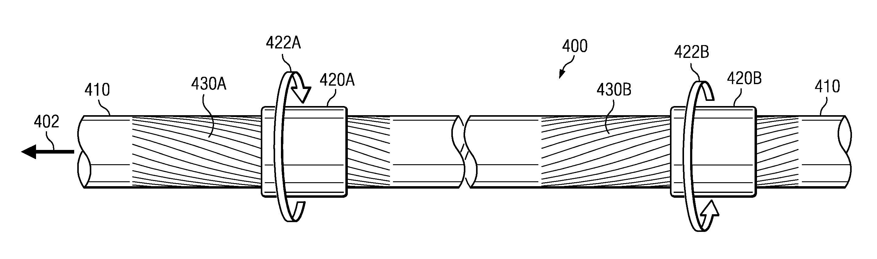
embodiment 400

[0035]While the tool embodiment 400 disclosed on FIGS. 5A and 5B depicts first and second standoff rings 420A and 420B, it will be understood that downhole tool 400 may also include three or more standoff rings deployed about the tool body. For example, downhole tool 400 may include at least first, second, third, and fourth standoff rings engaging corresponding first, second, third, and fourth sets of helical grooves in the outer surface of the tool body with adjacent ones of the standoff rings being configured to rotate in opposite directions with respect to the tool body.

[0036]Although not shown, standoff rings 420A and 420B include internal helical grooves (or threads) sized and shaped to engage corresponding helical grooves 430A and 430B on the tool body 410 such that relative axial motion of the standoff rings 420A and 420B with respect to the tool body 410 causes a corresponding relative rotational motion. The standoff rings may optionally be spring biased towards one end of t...


PUM


Abstract

A first wireline tool embodiment includes a segmented tool body having a joint deployed between each adjacent pair of tool body sections. The joint may be configured to extend axially (causing a relative axial displacement of the adjacent tool body sections) when the wireline tool is subject to an axial load. The joint may include, for example, a compliant joint or a protractible joint. The joint may be further configured to cause a relative rotation between the adjacent tool body sections when the wireline tool is subject to axial load. A second wireline tool embodiment includes a plurality of standoff rings deployed about an outer surface of a rigid tool body. The standoff rings engage helical grooves in the outer surface of the tool body such that axial displacement of the tool body causes the standoff rings to rotate.

Description

CROSS REFERENCE TO RELATED APPLICATIONS[0001]None.FIELD OF THE INVENTION[0002]Disclosed embodiments relate generally to a downhole tools configured to have improved retrievability in differential sticking environments. More particularly, certain of the disclosed embodiments relate to a downhole tool including a segmented tool body in which the body segments are connected to one another via compliant and / or protractible joints that enable adjacent segments to translate with respect to one another. Other disclosed embodiments relate to a downhole tool including at least first and second standoff rings deployed about a rigid tool body.BACKGROUND INFORMATION[0003]The interaction force between the borehole wall and wireline tools or other downhole tools can become significant as a result of differential sticking phenomena. During open-hole wireline operations, the wellbore is typically pressurized above the formation pore pressure in order to prevent formation fluids from entering the we...

Claims


Application Information

Patent Timeline
Patent Type & Authority Patents(United States)
IPC IPC(8): E21B31/00E21B41/00E21B17/07E21B47/00E21B23/14
CPCE21B41/00E21B17/07E21B23/14E21B31/00E21B47/00E21B31/035
Inventor OCALAN, MURATPABON, JAHIR
Owner SCHLUMBERGER TECH CORP
Why Eureka
Try Eureka