Cable locking device

a locking device and cable technology, applied in the direction of cables, mechanical equipment, vehicles/pulleys, etc., can solve the problems of reducing the possibility of securing the length of the wire, and not always easy to release the grip on the wire. , to achieve the effect of reducing the principal stress and being convenient to apply

Active Publication Date: 2015-11-17
ERICO INT
View PDF109 Cites 6 Cited by
  • Summary
  • Abstract
  • Description
  • Claims
  • Application Information

AI Technical Summary

Benefits of technology

[0011]According to an aspect of the invention, a device has a plurality of wedging means, which lower initial loading friction by replacing action of cable sliding on housing with only smooth wedges sliding on the housing. This action increases the speed of engagement on the cable. Another benefit of multiple jaws is an increase in gripping area, reducing stress and increasing opportunity to grip.
[0012]According to another aspect of the invention, a flexible jaw carrier / cage contains wedging means for release by push or pull without the potential for accidental loss of load.
[0013]According to yet another aspect of the invention, distribution of stress is handled through arrangement of loads. These loads include a tension load, due to object being suspended, that is in a direction Y. Clamping load due to the jaw wedging pressure is in a direction Z. Loading from a widely spread cable, surrounding a large object or object in close proximity to the device, is in a direction X. Directions X, Y, and Z are orthogonal, and equivalent to a standard 3-axis coordinate system. This distribution of stress into multiple directions reduces the principle stresses within the housing, allowing for a smaller design and thinner housing.
[0016]According to a still further aspect of the invention, an unlocking mechanism of the device is easier to apply with one hand or while wearing gloves than other solutions.
[0017]According to another aspect of the invention, a cable locking device includes: a housing; and at least two jaws within the housing. The housing includes a tapered section that engages the jaws to press the jaws inward. The device may include one or more of the following features: a carrier passing through the housing, for receiving a cable therein; the carrier is a tube; the carrier is flexible; the carrier is made of plastic; the carrier extends out of both ends of the housing; the carrier can be pushed to release the cable; the carrier can be pulled to release the cable; the carrier can be pushed or pulled to release the cable; the jaws are located in openings in the carrier; the carrier includes retention means for retaining the carrier partially within the housing; the jaws have gripping inner surfaces; the jaws have toothed inner surfaces for engaging the cable; the engagement of the jaws with the tapered section; wedging means engagement of jaws that engage cable, and that are engaged with housing; a spring within the housing biases the carrier such that the jaws engage the tapered section of the housing; the housing has two cable-receiving openings for receiving and securing different parts of the cable (or different cables); a secondary locking mechanism for securing the device from release; the secondary locking mechanism includes a locking screw that is tightened to prevent release of the jaws under seismic, or other intermittent loading condition; the secondary locking mechanism includes a locking screw that has a shear-off head; and / or the device distributes stress through arrangement of loads along different axes, for example reducing principal stresses within the housing.

Problems solved by technology

The problem with both is that the bottom or free end of the length of wire or cable has to be passed over the structural object, through the loop on the upper end, and then pulled tight.
If the cleat is on the wire, it may have to be removed and reattached, particularly if there is a clearance problem above or through the structural object.
The thread-through loop system of the prior patents also limits the possibility of securing the length of wire to the suspended or stayed object first, and then to the structure for final adjustment.
If adjustment or repositioning is required, it is not always easy to release the grip on the wire, or a special tool may be required.
Due to the difficulty in releasing the jam cleat to lower a suspended load, most installers position their suspended assemblies low and raise the cable through the device slowly in the free direction of the jam cleat or bearings until they reach the desired elevation.
In some circumstances, installers have not been educated on this approach.
These extra motions during the installation are time consuming, with little value added.

Method used


Image

  • Cable locking device
  • Cable locking device
  • Cable locking device

Examples


Embodiment Construction

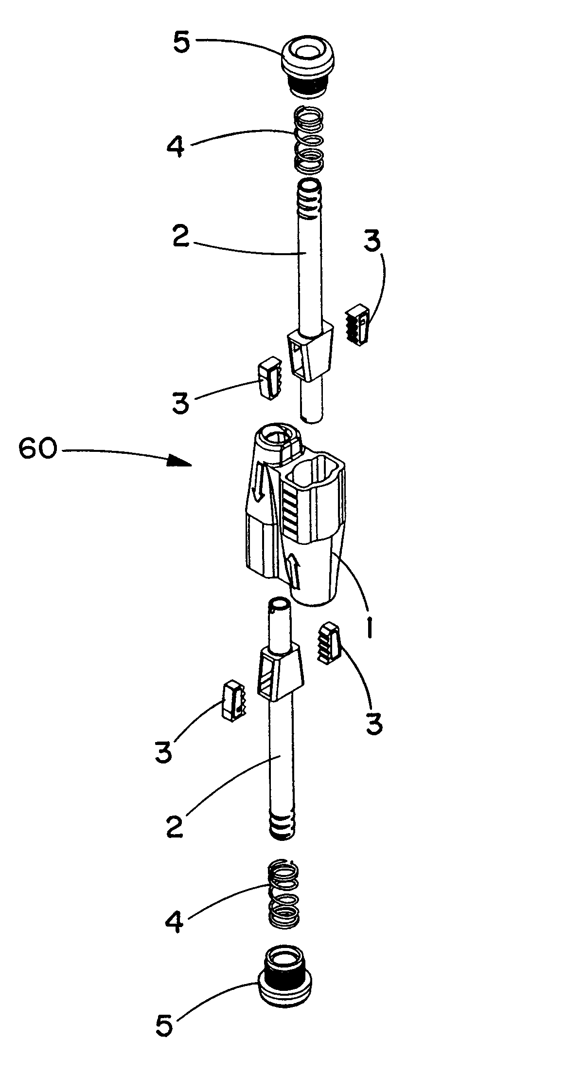
[0045]A device is used for gripping and securing cable for the purpose of suspending objects or loads. The device may be a two-barrel device that allows the user to create a loop of cable to secure to a hanging load, or to a structural member. The user of the locking device feeds the cable through one barrel, around an object to be suspended, and through the other barrel. The device has carriers installed in sockets in a housing, with wedge-shape jaws in openings in the carriers able to engage the cable and hold the cable within the device. Pushing or pulling of the carrier is used to release the spring force pressing the jaws inward, allowing the cable to be removed from the device.

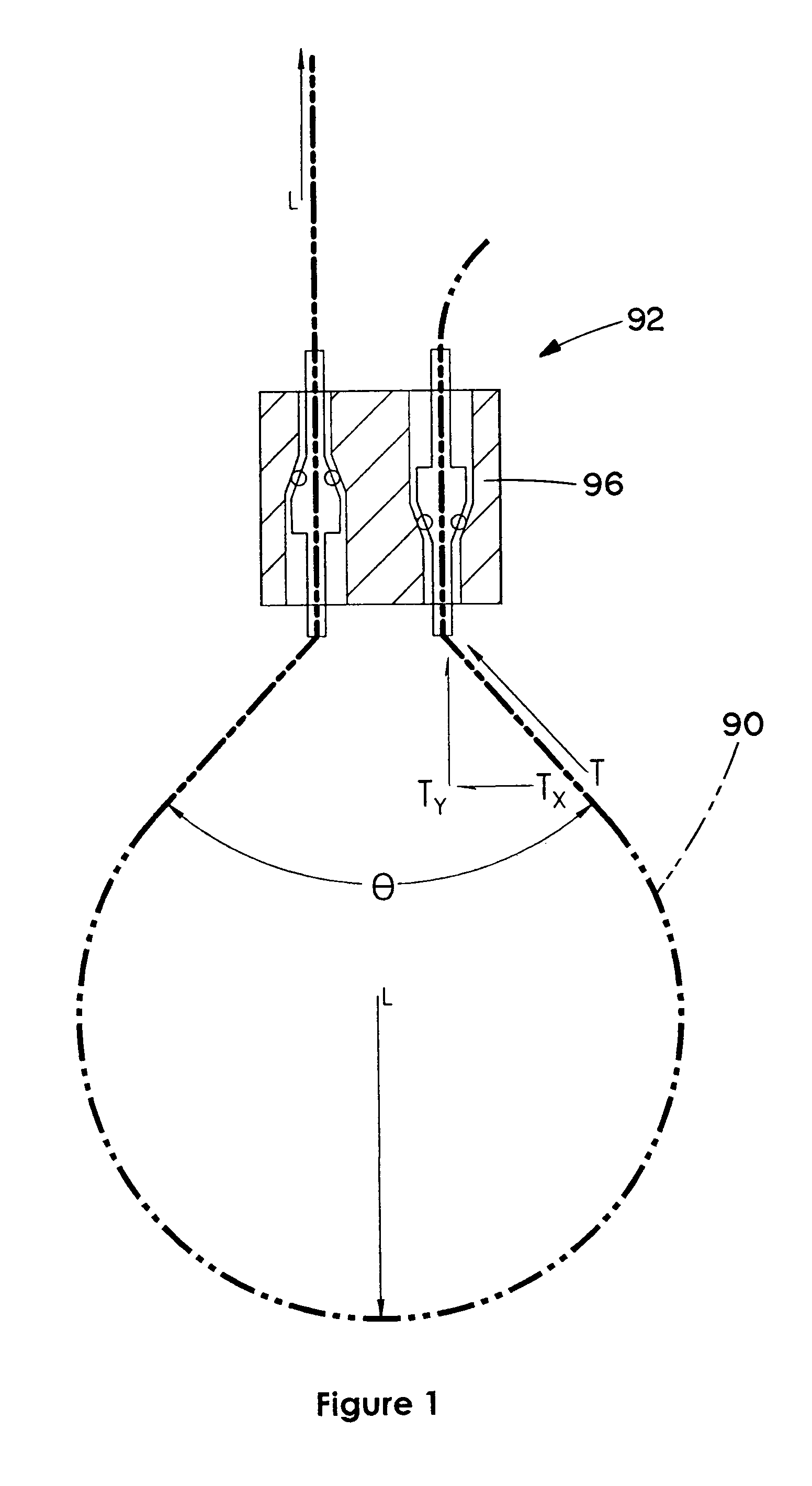
[0046]Referencing FIGS. 1 and 2, as an angle Θ of a securing cable 90 increases (the angle at which is located a securement device 92 to get around an object 94 to be secured, shown in FIG. 2), the force component Ty increases. In combination with the tension in the cable 90 from a suspended load, such a...


PUM

PropertyMeasurementUnit
angleaaaaaaaaaa
flexibleaaaaaaaaaa
forceaaaaaaaaaa

Abstract

A device is used for gripping and securing cable for the purpose of suspending objects or loads. The device may be a two-barrel device that allows the user to create a loop of cable to secure to a hanging load, or to a structural member. The user of the locking device feeds the cable through one barrel, around an object to be suspended, and through the other barrel. The device has carriers installed in sockets in a housing, with wedge-shape jaws in openings in the carriers able to engage the cable and hold the cable within the device. Pushing or pulling of the carrier is used to release the spring force pressing the jaws inward, allowing the cable to be removed from the device.

Description

[0001]This application claims the benefit under 35 USC 119 of U.S. Provisional Application 61 / 567,210, filed Dec. 6, 2011, which is incorporated herein by references in its entirety.TECHNICAL FIELD OF THE INVENTION[0002]This invention relates generally to cable locking devices for suspension systems, such as a system for suspending or hanging facilities such as cables, pipe, conduit, or duct, for example.DESCRIPTION OF THE RELATED ART[0003]In building construction and reconstruction, utilities and other facilities such as piping, conduit, duct, light fixtures, and communications wiring, for example, are commonly supported from building structural elements such as beams, purlins, trusses, roofs, or concrete floors above a suspended ceiling. These facilities are usually secured in place by a wide variety of hangers or suspenders, ranging from clips or clamps to wire or chain. Examples of such construction fasteners and hangers are sold under the well-known CADDY trademark by ERICO Int...

Claims


Application Information

Patent Timeline
Patent Type & Authority Patents(United States)
IPC IPC(8): F16G11/04F16G11/10F16L3/14H02G3/00H02G3/30
CPCF16G11/04F16G11/106F16L3/14H02G3/263H02G3/30Y10T24/3969Y10T29/49826
Inventor WILSON, ERIC JLAUGHLIN, RAYMOND SLYNCH, EDWARD JBENNETT, MATTHEW
Owner ERICO INT
Why Eureka
Try Eureka