
Carrier channel with element concentration gradient distribution and fabrication method thereof

a carrier channel and gradient technology, applied in the field of carrier channels, can solve the problems of only applying thermal diffusion process, increasing device thermal budget and production cost, and consuming time and energy in the diffusion process

Active Publication Date: 2015-11-24
NATIONAL TSING HUA UNIVERSITY
View PDF8 Cites 378 Cited by
  • Summary
  • Abstract
  • Description
  • Claims
  • Application Information

AI Technical Summary

Benefits of technology

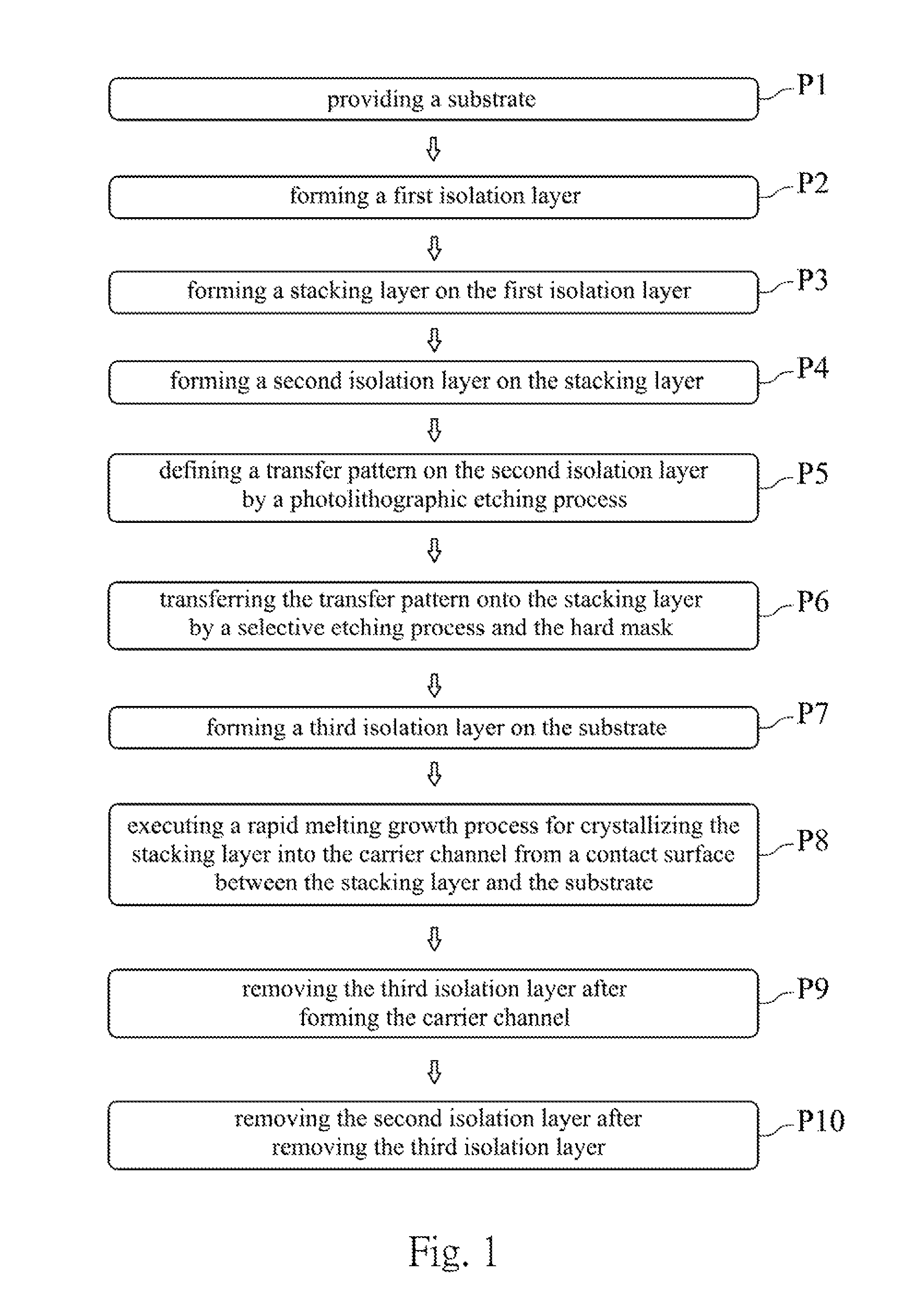
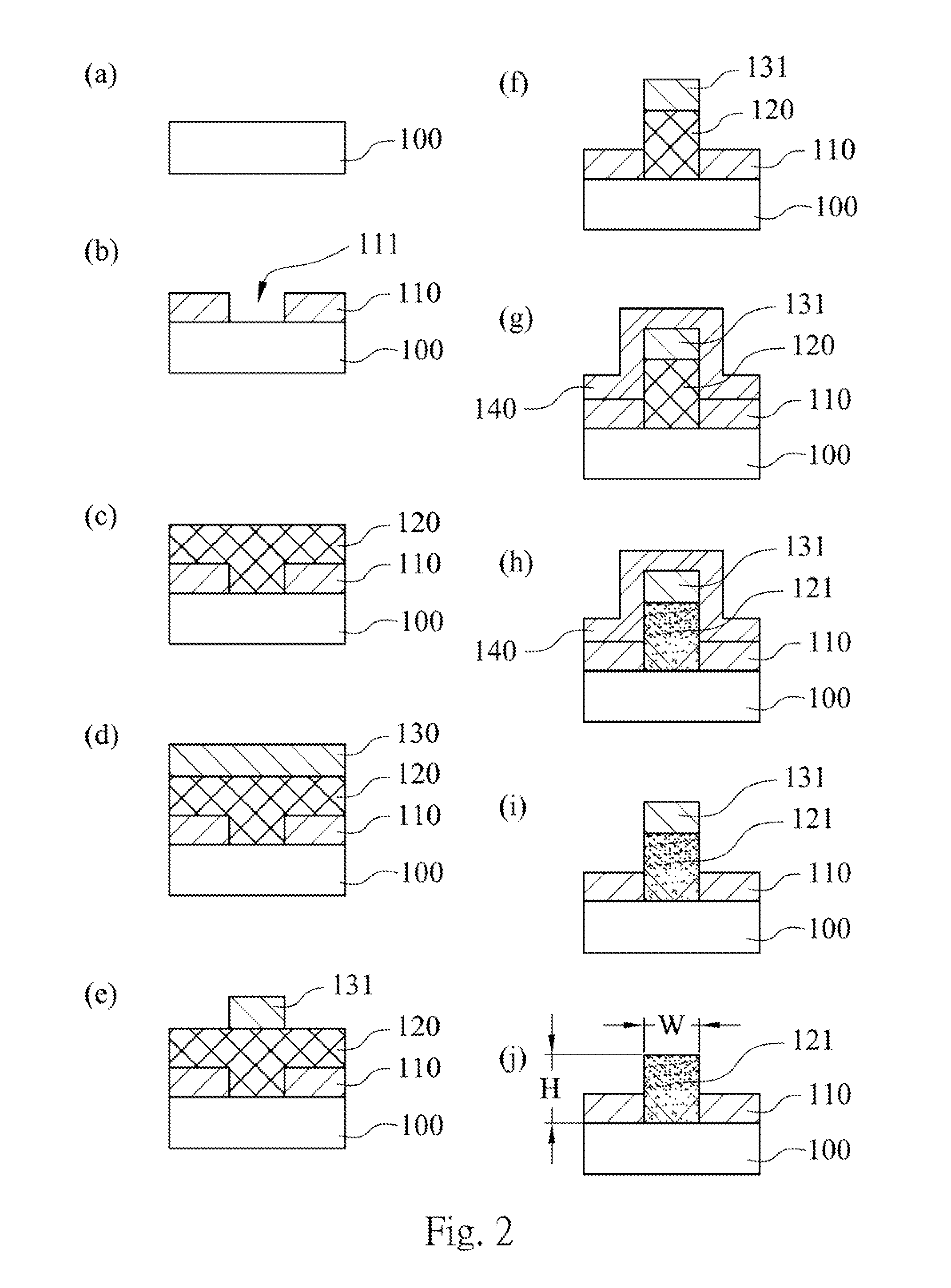
The patent text describes a method for making a carrier channel with an element concentration gradient distribution. The method involves forming a first isolation layer with a through hole, filling the through hole with a stacking layer that contacts the substrate, adding a second isolation layer, creating a transfer pattern on the second isolation layer, transferring the pattern onto the stacking layer, adding a third isolation layer, and executing a rapid melting growth process to crystallize the stacking layer. The resulting carrier channel has an element concentration gradient distribution. This method allows for the creation of structures with controlled element concentration gradients, which can be useful in a variety of applications such as electronics and optics.

Problems solved by technology

How to control the carrier concentration and the carrier location precisely is a concerned issue in the semiconductor industry.
But the thermal diffusion process consumes amount of time and energy, and it would increase the thermal budget and the production costs of the device significantly.
Furthermore, the thermal diffusion process is only applied to the shallow area of the device.
Because the carriers acceleration by the electric field has strong energy, the carriers would damage the surface lattice of the device and generate form a lattice defect.
Although the lattice defect can be repaired by executing an annealing process after the ion implantation process, but the annealing process increases the production costs of the device.
However, the high temperature annealing process always increases the production costs.

Method used


Image

  • Carrier channel with element concentration gradient distribution and fabrication method thereof
  • Carrier channel with element concentration gradient distribution and fabrication method thereof
  • Carrier channel with element concentration gradient distribution and fabrication method thereof

Examples


Embodiment Construction

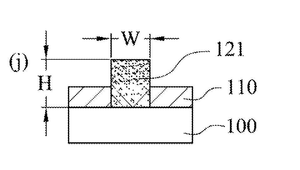
[0016]FIG. 1 is a flowchart of a fabricating method of a carrier channel with an element concentration gradient distribution according to one embodiment of the present disclosure, and the fabricating method includes the following steps.

[0017]Step P1, a substrate is provided and the substrate can be made of a single-layer material or a multilayer material which are compatible with a semiconductor process. Therefore, the carrier channel fabricated by the fabricating method can be integrated with the other semiconductor element on a chip. The substrate can be a monocrystalline silicon substrate, a polycrystalline silicon substrate or an amorphous silicon substrate.

[0018]Step P2, a first isolation layer is formed on the substrate and the first isolation layer has a first through hole. The first through hole is formed through the first isolation layer. The shape of the first through hole can be varied on demand. Furthermore, the first isolation layer can be an oxide layer or a nitride la...


PUM


Abstract

The present disclosure provides a carrier channel with an element concentration gradient distribution. The carrier channel includes a substrate and a carrier channel structure. The carrier channel structure is stacked on the substrate, wherein a ratio of a height and a width of the carrier channel is greater than 1, and the carrier channel is crystallized from the contact surface by a rapid melting growth process, thus the carrier channel structure has the element concentration gradient distribution.

Description

RELATED APPLICATIONS[0001]This application claims priority to Taiwan Application Serial Number 103116982, filed May 14, 2014, which is herein incorporated by reference.BACKGROUND[0002]1. Technical Field[0003]The present disclosure relates to a carrier channel and a fabricating method thereof. More particularly, the present disclosure relates to a carrier channel with an element concentration gradient distribution and a fabricating method thereof.[0004]2. Description of Related Art[0005]In semiconductor devices, the carrier concentration in the active region would affect the performance of the device. How to control the carrier concentration and the carrier location precisely is a concerned issue in the semiconductor industry.[0006]In the semiconductor industry, the thermal diffusion process and the ion implantation process have been widely used to control the carrier concentration and the carrier distribution. The thermal diffusion process promoted the carrier moving from high conce...

Claims


Application Information

Patent Timeline
Patent Type & Authority Patents(United States)
IPC IPC(8): H01L21/76H01L21/02H01L29/10H01L29/36
CPCH01L21/02667H01L21/02381H01L21/02642H01L29/1029H01L29/36H01L21/0245H01L21/02452H01L21/0251H01L21/02532H01L21/02535H01L29/1054
Inventor LEE, MING-CHANGTSENG, CHIH-KUO
Owner NATIONAL TSING HUA UNIVERSITY
Learn More