MIMO antenna for improved isolation

a technology of isolation and imitation antenna, applied in the direction of antenna, antenna details, antenna couplings, etc., can solve the problems of interference between radiators, large degraded reception signal reliability, and insufficient distance between multiple antennas, so as to achieve adequate isolation properties and improve isolation properties

Active Publication Date: 2015-11-24
MOBITECH +1
View PDF16 Cites 3 Cited by
  • Summary
  • Abstract
  • Description
  • Claims
  • Application Information

AI Technical Summary

Benefits of technology

[0019]An antenna according to an embodiment of the present invention can improve isolation properties between multiple antennas and can ensure adequate isolation properties even when the distances between multiple antennas are set to be relatively small.

Problems solved by technology

In a wireless communication environment, the reliability of reception signals may be greatly degraded by fading, shadowing, wave attenuation, interference, etc.
A MIMO antenna has an arrayed antenna structure that uses multiple radiators, and since a multiple number of radiators are used, there can be interference occurring between the radiators.
Such interference can distort the radiating pattern or create a mutual coupling effect among the radiators.
However, since the demand for smaller terminals is an ongoing requirement, and since providing a sufficient distance between multiple antennas not only is very difficult but also runs contrary to providing smaller terminal sizes, there is a need for an isolation technique that can be applied for multiple antennas that are positioned relatively closely to one another.

Method used


Image

  • MIMO antenna for improved isolation
  • MIMO antenna for improved isolation
  • MIMO antenna for improved isolation

Examples


Embodiment Construction

[0023]A MIMO antenna for improving isolation according to a preferred embodiment of the present invention will be described below in more detail with reference to the accompanying drawings.

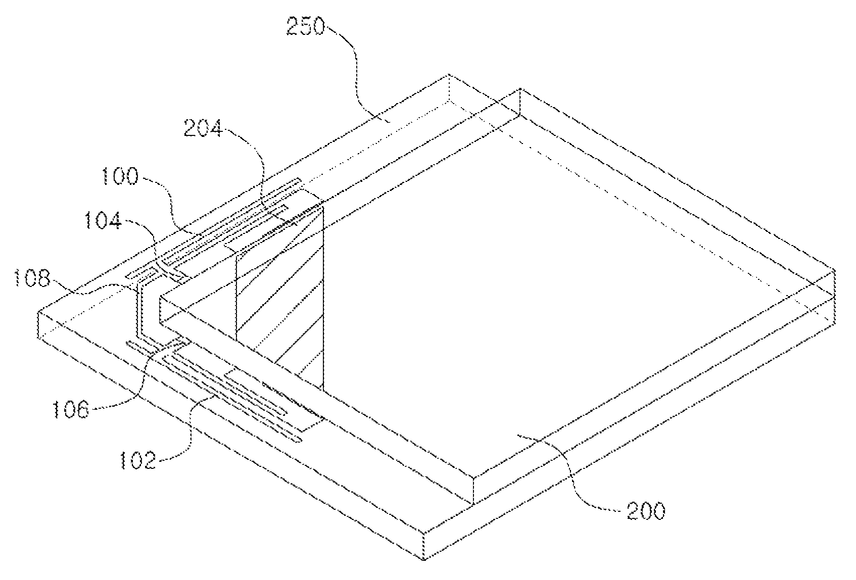
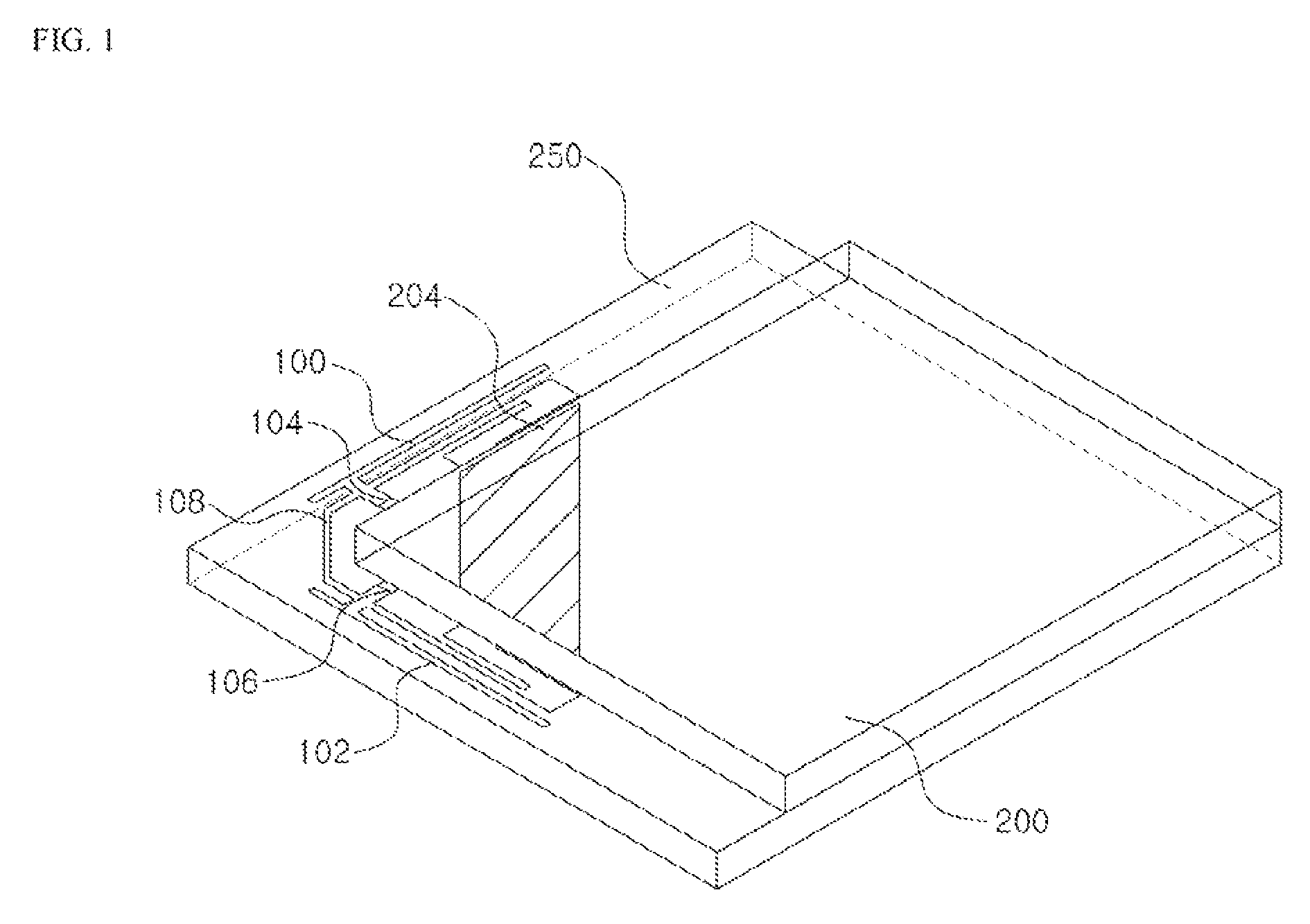
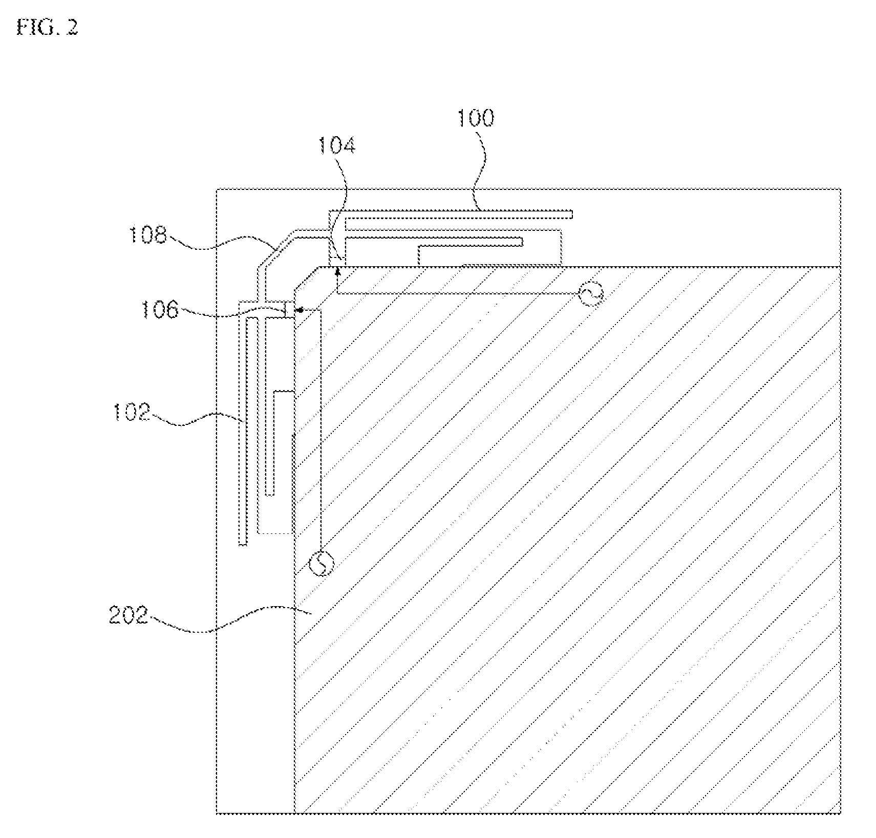
[0024]FIG. 1 is a perspective view of a MIMO antenna for improving isolation according to an embodiment of the present invention, FIG. 2 is a bottom view of a MIMO antenna for improving isolation according to an embodiment of the present invention, and FIG. 3 is a top view of a MIMO antenna for improving isolation according to an embodiment of the present invention.

[0025]Referring to FIG. 1 through FIG. 3, a MIMO antenna for improving isolation according to an embodiment of the present invention can include a first radiator 100, a second radiator 102, a first feed point 104, a second feed point 106, a connector line 108, a dielectric feature 200, a ground plane 202, and a coupling member 204.

[0026]The dielectric feature 200 may serve as the body to which the ground plane 202 and the coupling membe...


PUM


Abstract

A MIMO antenna for improving isolation is disclosed. The disclosed antenna includes a dielectric feature; a ground plane included in a first layer of the dielectric feature; a first radiator, which is electromagnetically joined with a first feed point, configured to radiate a first RF signal, and joined with the ground plane; a second radiator, which is electromagnetically joined with a second feed point, configured to radiate a second RF signal, and joined with the ground plane; and a connector line, which is joined with a particular point of the first radiator and with a particular point of the second radiator to connect the first radiator with the second radiator. The disclosed antenna can improve isolation properties between multiple antennas and can ensure adequate isolation properties even when the distances between multiple antennas are set to be relatively small.

Description

TECHNICAL FIELD[0001]The present invention relates to an internal antenna, more particularly to an internal antenna having improving isolation properties to prevent interference between antennas.BACKGROUND ART[0002]With the rapidly increasing demands for multimedia services, there is a demand for mobile communication systems to provide high-speed data transmissions in a reliable manner. In order to enable high-speed data transmission over a wireless channel, which uses limited bandwidth and power, it is essential to increase capacity. In recent times, there has been a continued increase of interest in technologies for improving capacity.[0003]In a wireless communication environment, the reliability of reception signals may be greatly degraded by fading, shadowing, wave attenuation, interference, etc. Thus, in order to enable high-speed data communication, these wireless channel properties must be overcome, or an alternative is required which utilizes such qualities. A technology pro...

Claims


Application Information

Patent Timeline
Patent Type & Authority Patents(United States)
IPC IPC(8): H01Q1/52H01Q9/42H01Q21/28
CPCH01Q1/521H01Q9/42H01Q21/28
Inventor KIM, JIN-MYUNGJUNG, CHANG-WONYEOM, IN-SU
Owner MOBITECH
Why Eureka
Try Eureka