Supercharge Your Innovation With Domain-Expert AI Agents!

Electric storage device management apparatus

a technology of electric storage devices and management apparatuses, which is applied in the direction of cell components, transportation and packaging, and the arrangement of several simultaneous batteries, etc., can solve the problems of insufficient capacity utilization, insufficient power storage in some electric storage devices, and insufficient charging of electric storage devices

Active Publication Date: 2015-11-24
GS YUASA INT LTD
View PDF12 Cites 7 Cited by
  • Summary
  • Abstract
  • Description
  • Claims
  • Application Information

AI Technical Summary

Benefits of technology

The invention is an electric storage device management system that monitors a group of electric storage devices that are charged and discharged by a charger / discharger. It includes a voltmeter to measure the voltage of each device, a discharging circuit to individually discharge the devices, and a controller to determine if there is an increase in voltage variation in each device and control the discharging circuit to balance the capacities of the devices. The invention allows for equalization of capacities among the electric storage devices.

Problems solved by technology

Therefore, some of the electric storage devices may not be fully charged.
Therefore, power stored in some of the electric storage devices may not be fully used.
Thus, if the capacities of the electric storage devices are not equal, those capacities cannot be fully utilized.
Therefore, the capacities may not be sufficiently equalized.
In the electric storage devices such as the secondary battery having a plateau region, the capacities of the electric storage devices may not be easily estimated based on voltage information of the electric storage devices obtained in the plateau region and, therefore, the capacities of the electric storage devices may not be properly equalized.

Method used


Image

  • Electric storage device management apparatus
  • Electric storage device management apparatus
  • Electric storage device management apparatus

Examples


first embodiment

[0022]A first embodiment will be described with reference to FIGS. 1 to 6.

[0023]1. Configuration of a Battery Management System

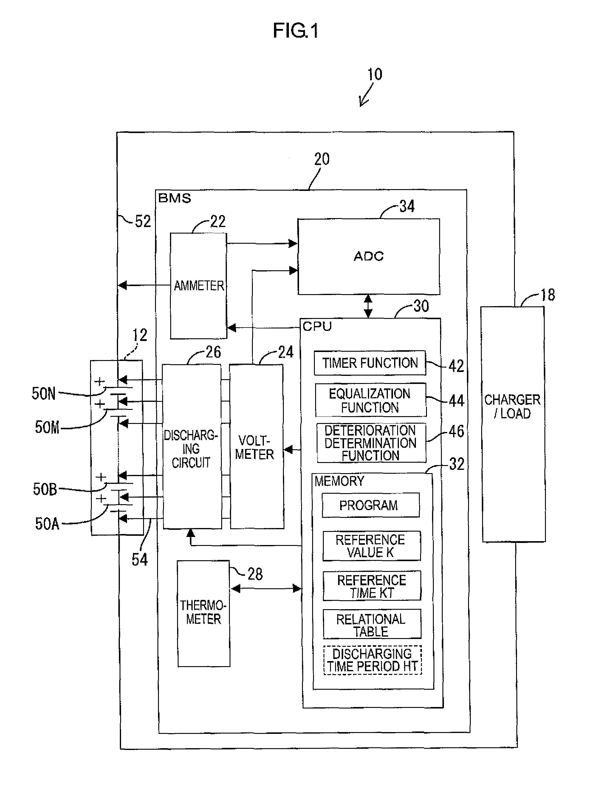
[0024]As illustrated in FIG. 1, a charging and discharging system 10 includes a battery assembly 12, a battery management system (EMS) 20, and a charger / load 18. The battery management system corresponds to an electric storage device management apparatus. The battery assembly 12 may be mounted on an electric vehicle. The battery assembly 12 includes a plurality of secondary batteries 50 (electric storage devices) connected in series. The charger / load 18 is provided inside or outside of the electric vehicle. The battery assembly 12 is charged with a constant current when connected to the charger of the charger / load 18. The battery assembly 12 is discharged with a constant current when connected to the load of the charger-load 18. The EMS 20 monitors voltages V and currents I of the secondary batteries 50 in the battery assembly 12 under charging. The EMS 20 c...

second embodiment

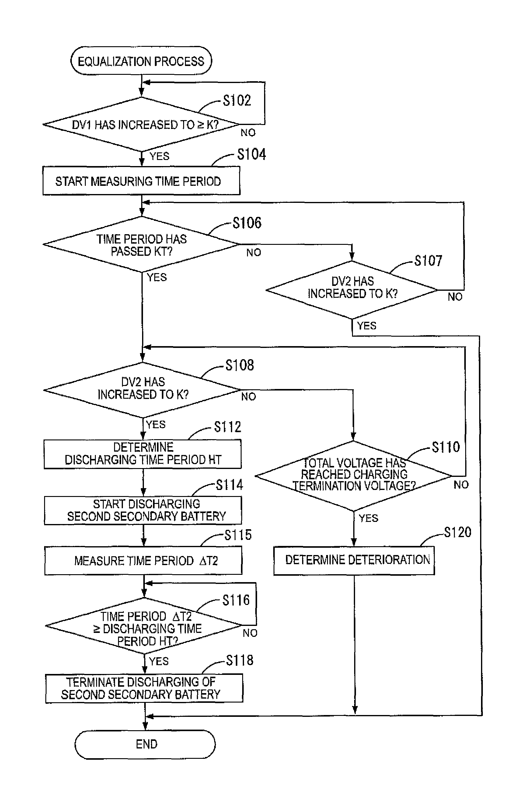
[0057]A second embodiment will be described with reference to FIG. 7. Specifically, an equalization process executed by the charging and discharging system 10 associated with a discharging control process will be described.

[0058]The battery assembly 12 is under constant discharging. In the following description, procedures in which the CPU 30 determines whether the voltage V has decreased to the reference voltage KV1 that is a voltage at the point KS1 and whether the unit time variation DV has increased to the reference value K will be explained.

[0059]Furthermore, as in the first embodiment, the secondary battery 50, the unit time voltage DV of which has increased to the reference value K the fastest, may be referred to as a first secondary battery 50. Furthermore, the secondary battery 50, the unit time voltage DV of which has increased to the reference value K the slowest, may be referred to as a second secondary battery 50. The equalization process for the first secondary battery...

fourth embodiment

[0085]A fourth embodiment will be described with reference to FIG. 9. An equalization process executed by the charging and discharging system 10 associated with the discharging control process will be explained.

[0086]In this embodiment, the point KS1 will be used. As in the first embodiment or the third embodiment, the secondary battery 50, the unit time voltage DV of which has increased to the reference value K the fastest, may be referred to as a first secondary battery 50. Furthermore, the secondary battery 50, the unit time voltage DV of which has increased to the reference value K the slowest, may be referred to as a second secondary battery 50. The same configurations as the first embodiment or the third embodiment will not be explained.

[0087]1. Equalization Process

[0088]The equalization process is executed according to a flowchart illustrated in FIG. 9. The CPU 30 determines whether the unit time variation DV2 has increased to the reference value K (S302). If the unit time va...


PUM


Abstract

An electric storage device management apparatus is provided for monitoring an electric storage device assembly including a plurality of electric storage devices connected in series. The apparatus includes a voltmeter, a discharging circuit, and a controller. The discharging circuit is configured to discharge the electric storage devices individually. The controller is configured to: determine whether a unit time variation in voltage of a first electric storage device has increased to a reference value and a unit time variation in voltage of a second electric storage device has increased to the reference value; measure an elapsed time period since the unit time variation of the first electric storage device has increased to the reference value; and control the discharging circuit to discharge the electric storage devices based on the elapsed time period such that capacities of the electric storage devices are equalized.

Description

CROSS REFERENCE TO RELATED APPLICATION[0001]This application claims priority from Japanese Patent Applications No.2011-197336 filed on Sep. 9, 2011 and No. 2012-186523 filed on Aug. 27, 2012. The entire content of these priority applications is incorporated herein by reference.TECHNICAL FIELD[0002]The invention disclosed in this specification relates to a technology of equalizing capacities of a plurality of electric storage devices under charging or discharging.BACKGROUND[0003]Rechargeable electric storage devices have been used. The electric storage devices can be repeatedly used by charging and discharging. Therefore, the electric storage devices are eco-friendly in comparison to non-rechargeable batteries and thus currently used in various fields including electric vehicles.[0004]In a device including a plurality of electric storage devices, capacities of the electric storage devices may not be equal due to variations in initial capacity or different deterioration speeds. Some o...

Claims


Application Information

Patent Timeline
IPC IPC(8): H02J7/00H02J7/02H01M4/58
CPCH02J7/0014Y02E60/122Y02E60/10
Inventor SHIRAISHI, TAKEYUKI
Owner GS YUASA INT LTD
Features
  • R&D
  • Intellectual Property
  • Life Sciences
  • Materials
  • Tech Scout
  • Unparalleled Data Quality
  • Higher Quality Content
  • 60% Fewer Hallucinations
Learn More