DC to DC converter producing output voltage exhibiting rise and fall characteristics independent of load thereon

a technology of dc-dc converter and output voltage, which is applied in the direction of dc-dc conversion, power conversion systems, instruments, etc., can solve the problem of difficult to finely control the rise of output voltage using only soft start control

Inactive Publication Date: 2000-11-14
FUJITSU LTD
View PDF12 Cites 36 Cited by
  • Summary
  • Abstract
  • Description
  • Claims
  • Application Information

AI Technical Summary

Benefits of technology

According to the present invention, when the power supply to each DC / DC apparatus is turned off, a synchronous rectifying transistor or a load capacitance discharging transistor provided in each DC / DC apparatus is forcibly turned off to discharge charges corresponding to the load capacitance. Thus, it is possible to remove the disadvantage in that a difference is made between the times required until the respective output voltages reach 0V.

Problems solved by technology

Accordingly, where the load is light, the rise of the output voltage relatively becomes early, and thus it is difficult to finely control the rise of the output voltage using only the soft start control.

Method used


Image

  • DC to DC converter producing output voltage exhibiting rise and fall characteristics independent of load thereon
  • DC to DC converter producing output voltage exhibiting rise and fall characteristics independent of load thereon
  • DC to DC converter producing output voltage exhibiting rise and fall characteristics independent of load thereon

Examples


Embodiment Construction

First, for better understanding of the preferred embodiments of the present invention, the related prior art will be explained with reference to FIGS. 1a to 9.

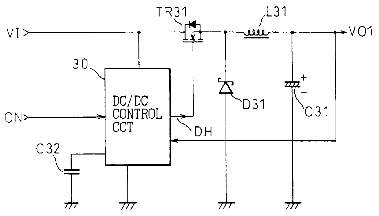
FIG. 1a shows the circuit constitution of a DC / DC apparatus used in an ordinary hand-held type personal computer or the like.

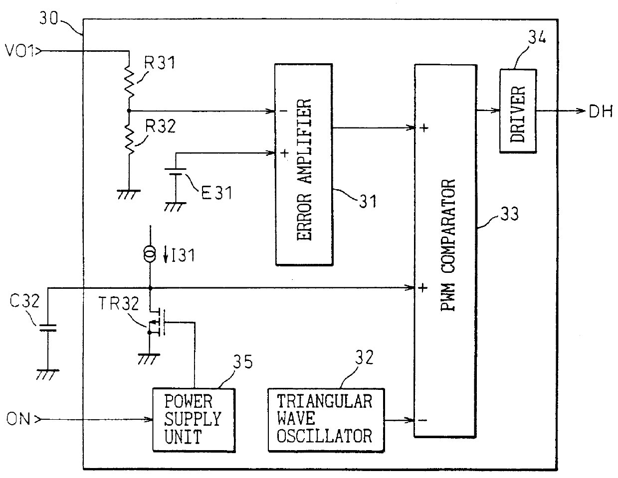
In FIG. 1a, reference ON denotes an on / off control signal for indicating a start (on) or a stop (off) of the operation of the DC / DC apparatus, and reference 30 denotes a DC / DC control circuit using a PWM control and responsive to the on / off control signal ON. Under control of the DC / DC control circuit 30, the DC / DC apparatus starts its operation when the on / off control signal ON is at "H" level, and stops its operation when the on / off control signal ON is at "L" level. Also, reference TR31 denotes a switching transistor which is turned on / off in response to an output DH of the DC / DC control circuit 30; reference L31 denotes a choke coil for converting an input voltage VI to an output voltage VO1; referen...


PUM


Abstract

A direct-current to direct-current conversion (DC/DC) apparatus includes a control circuit having an error amplifier for voltage control and controlling a direct-current to direct-current conversion based on a pulse width modulation control using an output of the error amplifier. The error amplifier inputs a voltage signal corresponding to an output voltage of a DC/DC result and a plurality of reference voltage signals. The DC/DC apparatus also includes a soft start capacitor to provide one of the plurality of reference voltage signals. The error amplifier amplifies a difference between the voltage signal corresponding to the output voltage of a DC/DC result and a voltage signal of a lower potential among the plurality of reference voltage signals and, based on the amplified output, carries out the pulse width modulation control. Furthermore, the control circuit includes a circuit for discharging charges corresponding to the output voltage of the DC/DC result when a power supply to the control circuit is turned off. By the constitution, it is possible to easily realize power turn-on/turn-off sequence controls without requiring any special logic circuit, and thus to control rise/fall characteristics of the output voltage without depending on the load.

Description

BACKGROUND OF THE INVENTION1. Field of the InventionThe present invention relates to a power supply circuit used in various kinds of electronic apparatuses. More particularly, it relates to a circuit for controlling a direct-current to direct-current conversion so as to keep constant a voltage or voltages used in an electronic apparatus, and to a direct-current to direct-current conversion apparatus using the same. Note that, in the description below, "direct-current to direct-current conversion" is simply abbreviated as ""DC / DC"".2. Description of the Related ArtA portable electronic apparatus such as a so-called hand-held type personal computer is equipped with a battery as its power source. Since the voltage of a battery is generally lowered as the battery discharges, a DC / DC apparatus is incorporated into the electronic apparatus so as to keep constant the output voltage of the battery.On the other hand, the power source used in an electronic apparatus usually requires a plurali...

Claims


Application Information

Patent Timeline
Patent Type & Authority Patents(United States)
IPC IPC(8): H02M1/00H02M3/155G05F1/40H02M1/36H02M3/156
CPCH02M1/36H02M3/156H02M2001/008H02M1/008
Inventor SAEKI, MITSUOYANO, HIDETOSHIOZAWA, HIDEKIYOKITAGAWA, SEIYAMATSUYAMA, TOSHIYUKIMATSUMOTO, TAKASHITAKIMOTO, KYUICHISANO, YOSHIAKI
Owner FUJITSU LTD
Why Eureka
Try Eureka