Deflection resistant combination turn plate and slip plate

a technology of combination turn plate and slip plate, which is applied in the direction of lifting devices, lifting frames, etc., can solve the problems of reducing the accuracy of measurements acquired during rolling compensation procedures, and achieve the effect of reducing undesired reactions

Active Publication Date: 2015-12-01
HUNTER ENG
View PDF11 Cites 0 Cited by
  • Summary
  • Abstract
  • Description
  • Claims
  • Application Information

AI Technical Summary

Benefits of technology

[0012]In a further embodiment, the present disclosure sets forth an improved slip plate assembly for supporting the rear wheels of a vehicle on a precision planar surface. The slip plate is supported on a base plate by an array of bearings, and is configured for a limited range of translational and rotational movement within the plane of the precision surface by a guide pin and longitudinally spaced cam roller in engagement with the base plate. The guide pin extends vertically downward from the slip plate and into an open region defined by a notched portion of the base plate. Interaction between the guide pin and the peripheral edges of the notched region serve to define the limits of rotational and translational movement for the slip plate. Correspondingly, at the opposite longitudinal end of the slip plate from the guide pin, the cam roller is disposed below the underside surface of the slip plate, and is seated within a transverse slot in the base plate. The interaction between the cam roller and the transverse slot permits a limited range of lateral movement of the slip plate, while preventing longitudinal movement. A limited range of rotation motion of the slip plate about the axis of the cam roller within the transverse slot is regulated by the interaction between the guide pin and peripheral edge of the notched region in the base plate at the opposite longitudinal end of the slip plate.
[0013]In a further embodiment, the present disclosure sets forth a combination slip plate and turn plate assembly for support of the steered wheels of a vehicle on a precision planar surface in which the turn plate is disposed between opposite longitudinal ends of the slip plate. The assembly includes a common base plate on which both the slip plate and the turn plate are supported by associated bearing assemblies to establish a planar surface within an established measurement tolerance. The slip plate is configured for limited translational movement relative to the base plate surface on which it is supported, while the turn plate is configured for both limited translational movement relative to the base plate supporting surface and for rotational movement in the same plane about a central axis. Translational movement of the slip plate and turn plate relative to the base plate is synchronized by respective connections to a common tie bar disposed within a recessed portion of the base plate. Spacing between longitudinally forward and longitudinally rearward peripheral edges of the turn plate and the adjacent portions of the slip plate is minimized by providing the adjacent portions of the slip plate with concave curvature adapted to the radial dimension of the adjacent turn plate.
[0014]In a further embodiment, the combination slip plate and turn plate assembly includes at least two transverse cam bars disposed to selectively support the slip plate segments and the turn plate against the base plate within adjacent longitudinal regions between adjacent bearing assemblies. Each cam bar is selectively adjusted between a supporting state and a relaxed state. In the supporting state, each cam bar is rotated into engagement with the upper surface of the base plate and the lower surfaces of both the slip plate segment and turn plate, functioning as a rigid support member for distributing loads from the slip plate segment and turn plate to the base plate. In the relaxed state, the cam bar is rotated out of engagement with the lower surfaces of the slip plate and the turn plate, permitting interference-free translational movement of the respective plates.

Problems solved by technology

In particular, it has been found that the rolling of the vehicle wheel assembly over the gap between the runway surface and the edge of the turn plate and / or slip plates can induce undesired reactions in the vehicle suspension system, and correspondingly, reduce the accuracy of measurements acquired during the rolling compensation procedures.

Method used


Image

  • Deflection resistant combination turn plate and slip plate
  • Deflection resistant combination turn plate and slip plate
  • Deflection resistant combination turn plate and slip plate

Examples


Embodiment Construction

[0031]The following detailed description illustrates the invention by way of example and not by way of limitation. The description enables one skilled in the art to make and use the present disclosure, and describes several embodiments, adaptations, variations, alternatives, and uses of the present disclosure, including what is presently believed to be the best mode of carrying out the present disclosure.

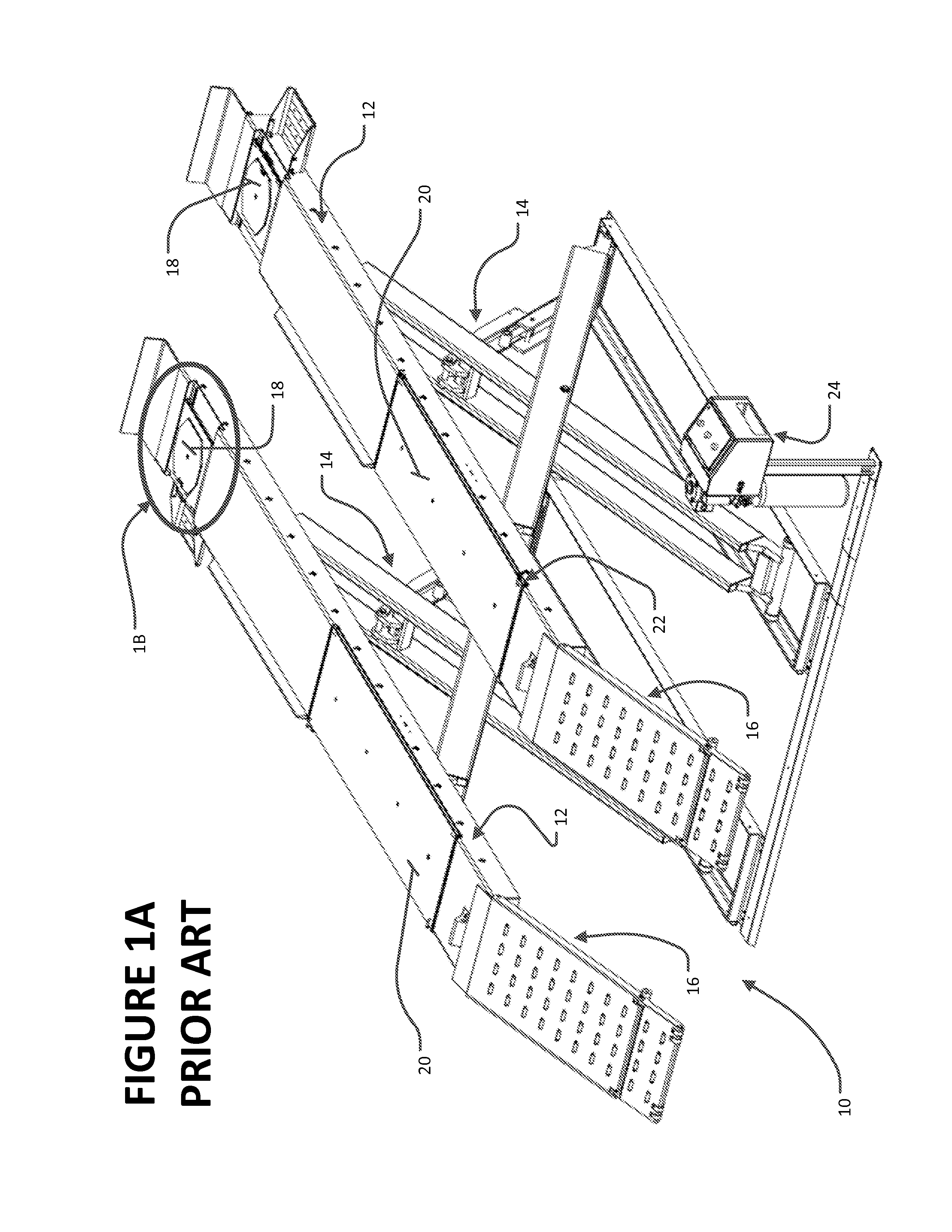
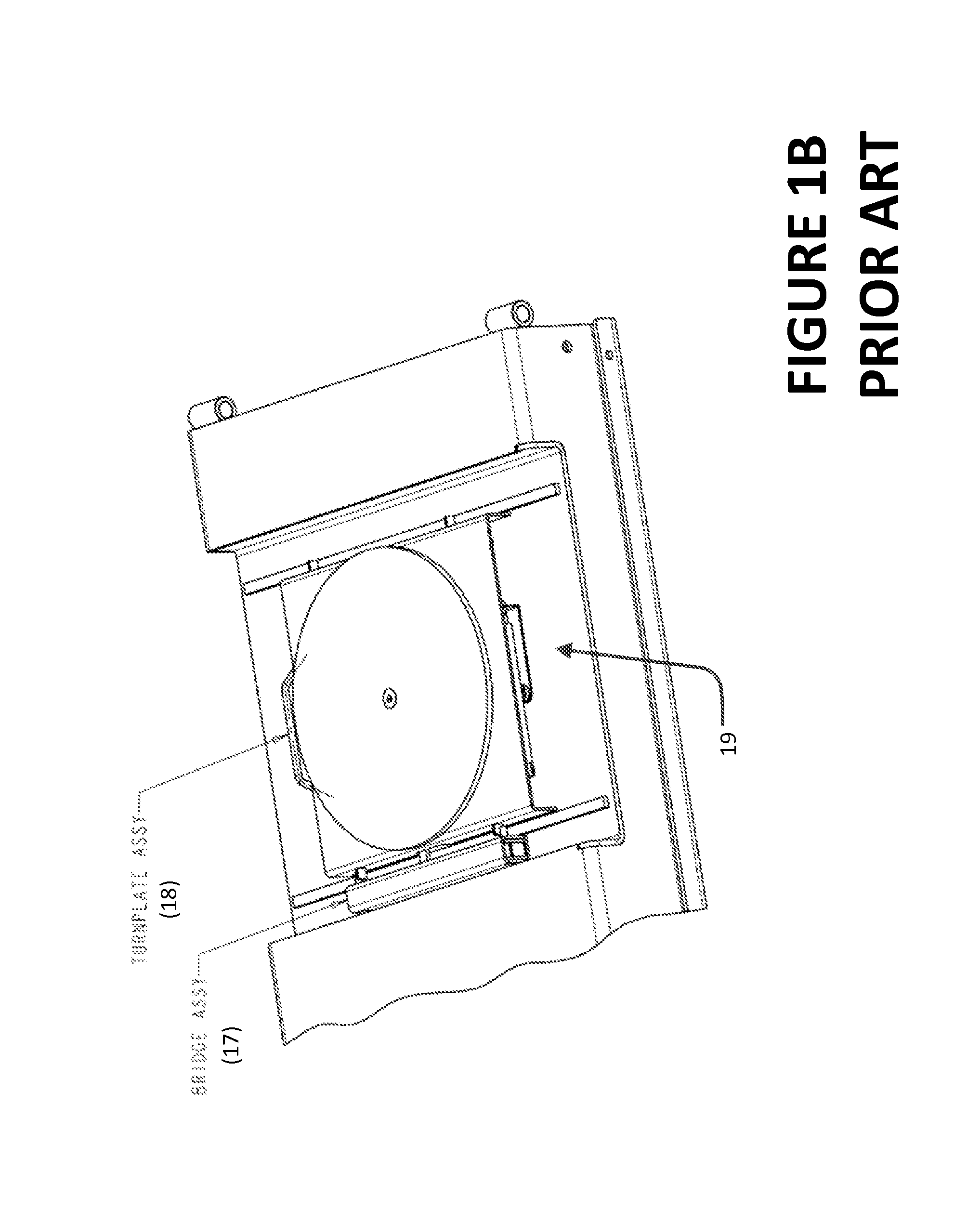
[0032]Turning to FIGS. 1A and 1B, a prior art vehicle support system is shown generally at 10. The vehicle support system 10 consists of an underlying surface, which may be for example, a supporting floor or an identical pair of adjacent runways 12, each configured to support the wheels for one side of a vehicle. Each runway 12 is optionally mounted on a lift structure 14, which forms no part of the present invention, such as a hydraulically actuated scissor mechanism. During use with runways, a vehicle is driven onto the runways 12 via a pair of inclined ramps 16 at the rear of the...


PUM


Abstract

A deflection resistant combination slip plate and turn plate assembly for support the steered wheels of a vehicle on a precision planar surface resistant to deflection and distortion. The slip plate and the turn plate are supported on an underlying surface by bearing assemblies, and establish a upper planar surface with the turn plate disposed in a cutout region of the slip plate. Each plate is configured for limited translational movement relative to the base plate surface on which it is supported, while the turn plate is further configured for rotational movement about a central axis. Translational movement of the plates is synchronized. Spacing between the slip plate and turn plate is minimized, and supporting means are provided to maintain the slip plate and turn plate in vertical alignment under load.

Description

CROSS-REFERENCE TO RELATED APPLICATIONS[0001]The present application is related to, and claims priority from both U.S. Provisional Patent Application Ser. No. 61 / 737,989 filed Dec. 17, 2012, and U.S. Provisional Patent Application Ser. No. 61 / 763,145 filed Feb. 11, 2013, each of which is herein incorporated by reference.STATEMENT REGARDING FEDERALLY SPONSORED RESEARCH[0002]Not Applicable.BACKGROUND OF THE INVENTION[0003]The present invention relates generally to automotive service equipment incorporating vehicle wheel turn plates and slip plates, such as vehicle support systems and vehicle lift racks, and in particular, to a deflection resistant combination of a vehicle wheel turn plate and slip plate establishing a precision planar surface for receiving a vehicle steered wheel.[0004]Typically, movable surfaces commonly referred to as turn plates and slip plates are placed on a vehicle support system surface onto which a vehicle undergoing an alignment measurement or adjustment proc...

Claims


Application Information

Patent Timeline
Patent Type & Authority Patents(United States)
IPC IPC(8): B66F7/28
CPCB66F7/28
Inventor OLSEN, MICHAEL A.NELGNER, WILLIAM JAMESSTREGE, TIMOTHY A.COLARELLI, III, NICHOLAS J.
Owner HUNTER ENG
Why Eureka
Try Eureka