Ristau conical rotor orbital engine

a conical rotor and orbital engine technology, applied in the direction of machines/engines, oscillating piston pumps, liquid fuel engines, etc., can solve the problems of limited commercial acceptance, significant increase in engine complexity and manufacturing costs, and most rotary engines suffer. , to achieve the effect of minimising engine size, weight, and maximum engine efficiency

Active Publication Date: 2015-12-01
RISTAU JUDSON PAUL
View PDF20 Cites 1 Cited by
  • Summary
  • Abstract
  • Description
  • Claims
  • Application Information

AI Technical Summary

Benefits of technology

[0008]The disadvantages of traditional rotary engines are overcome by the present document describing an improved Ristau Orbital Engine operating on a pressure differential. The Ristau Orbital Engine being adaptable to a wide range of pressure differentials that are naturally occurring or fuel generated. The Ristau Orbital Engine is well-suited for many applications for maximum engine efficiency, reliability, and smoothness of operation coupled with a minimum engine size, weight, and complexity.
[0009]The Ristau Orbital Engine is hereinafter disclosed which more fully combines the benefits and advantages of a reciprocating engine with the benefits and advantages of a turbine further incorporating less working components and improved efficiency.

Problems solved by technology

Most rotary engines also suffer, however, from one or more significant disadvantages which have severely limited their commercial acceptance.
The type of rotary engine most commonly produced at this time utilizes an Otto cycle and an eccentric rotor, which significantly increases the complexity and manufacturing costs of the engine.
Other rotary engines utilize a complex arrangement of planetary gears and cranks to operate connecting arms, multiple crankshafts, or sophisticated rhombic drives, thereby making the engine difficult to balance and expensive to manufacture.
The high volumetric displacement required for the constant pressure heating and cooling of this cycle, however, significantly increases the size of the engine and thus limits the practicality of utilizing this cycle for most applications.
The efficiency of the Otto cycle internal combustion engine is limited, however, by the temperature of the incoming gas.
The efficiency of an engine utilizing the Otto cycle cannot, however, be continually increased by raising the temperature of the incoming gas, since gas temperature must be kept sufficiently low in order to prevent detonation (knocking) which severely detracts from engine performance.
The complexity, wear, and increased balancing problems created by this offset axis arrangement thus substantially detract from the previously disclosed benefits of a rotary engine.

Method used


Image

  • Ristau conical rotor orbital engine
  • Ristau conical rotor orbital engine
  • Ristau conical rotor orbital engine

Examples


Embodiment Construction

[0049]Although the disclosure hereof is detailed and exact to enable those skilled in the art to practice the invention, the physical embodiments herein disclosed merely exemplify the invention, which may be embodied in other specific structure. The scope of the invention is defined in the claims appended hereto.

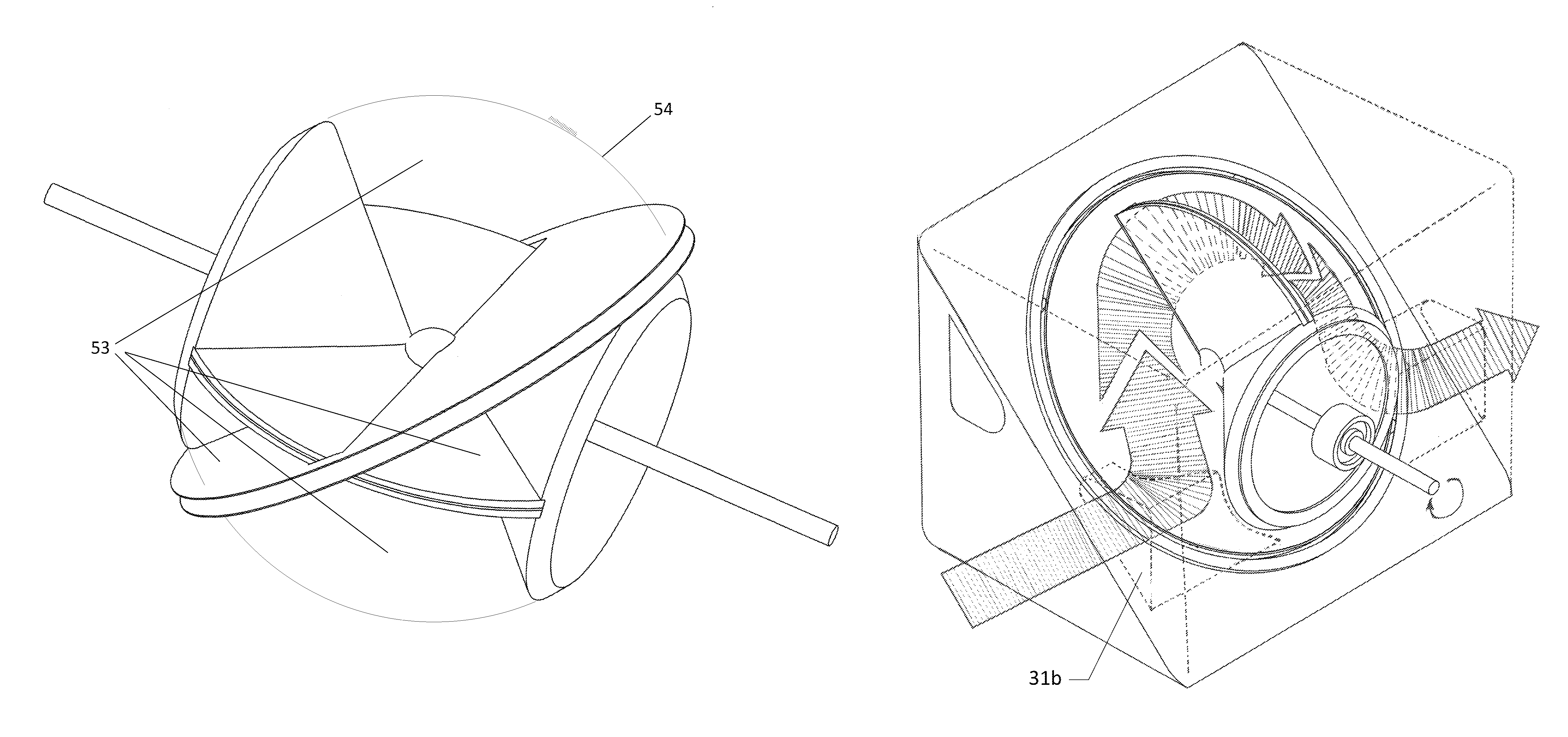
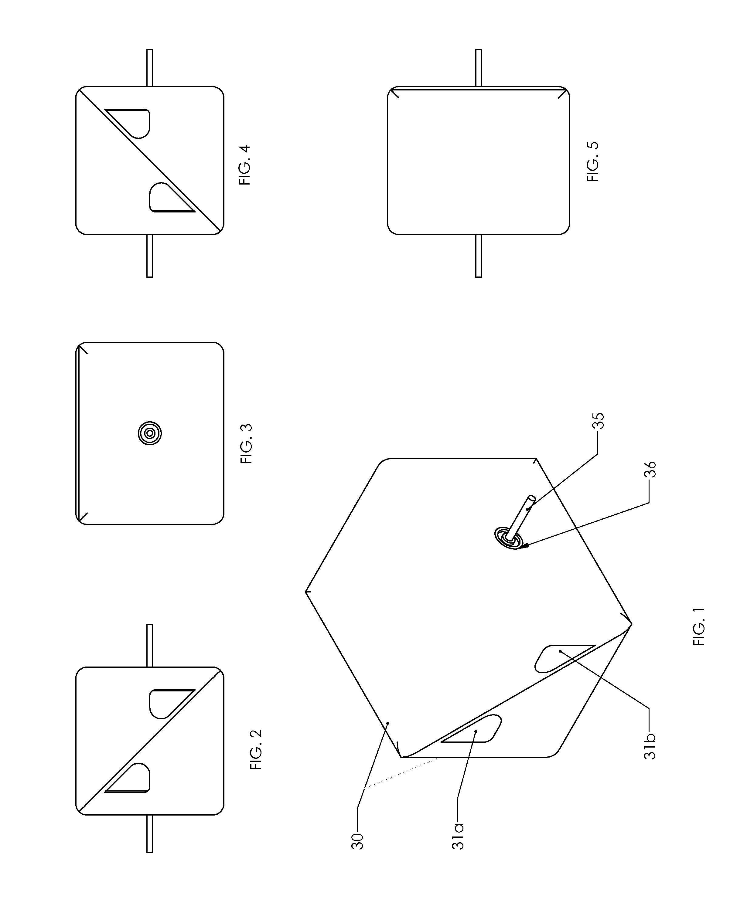
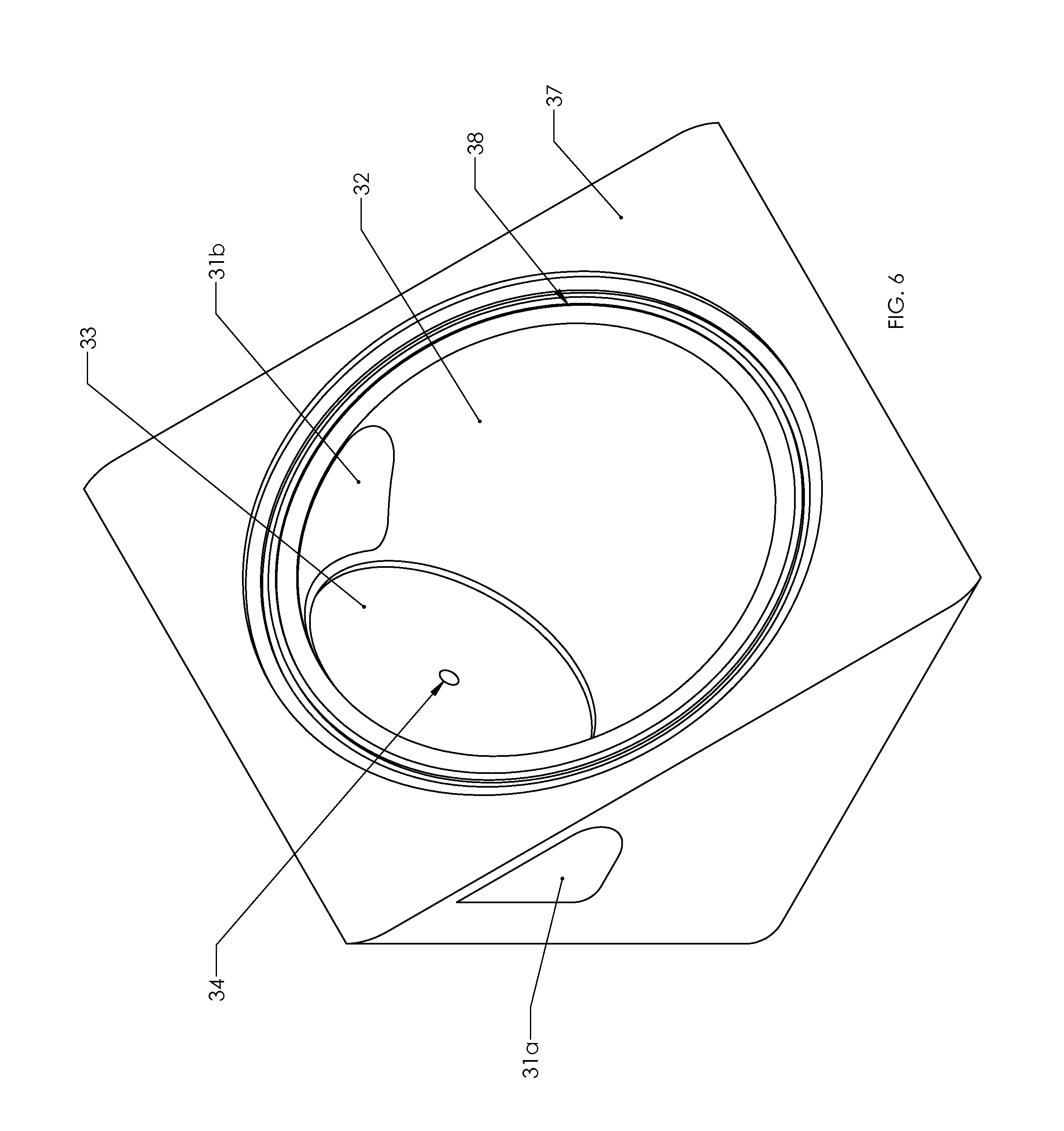
[0050]FIGS. 1-5 illustrate multiple views of one embodiment of the Ristau Orbital Engine of the present invention, wherein FIG. 1 illustrates the Ristau Orbital Engine in assembled configuration. The Ristau Orbital Engine has a block 30 which is comprised of two symmetrical halves, wherein one half block is shown in FIG. 6. The block 30 is comprised of a square box or rectangular like configuration. However, it is contemplated within the scope of the invention that the bock may take on any shape, size, configuration, or dimension, including but not limited to rectangular, cylindrical, triangular, square, ellipsoid, parallelogram, or any polygon configuration having three or ...


PUM


Abstract

A rotary thermal engine for generating mechanical energy. The rotary thermal engine includes an engine block having an enclosed interior space, a first rotor and a second rotor, a first disc coupled to the first and second rotor. A second disc is positioned between the first and second rotor, wherein the second disc pivots relative to the first disc. In addition, wherein the first and second rotors and first and second discs are at least partially enclosed within the interior space of the engine block.

Description

CROSS REFERENCE TO RELATED APPLICATIONS[0001]This application claims the benefit of U.S. Provisional Application No. 61 / 705,052 filed on Sep. 24, 2012, which is incorporated herein by reference in its entiretyFIELD OF THE INVENTION[0002]The present invention relates generally to thermodynamic cycle heat engines. In particular, the present invention is an apparatus and method for utilizing fluid pressure to drive dual adjacent rotating cones in conjunction with a rotating disc in order to generate mechanical energy or electrical energy.BACKGROUND[0003]This section is intended to introduce the reader to aspects of art that may be related to various aspects of the present invention, which are described and / or claimed below. This discussion is believed to be helpful in providing the reader with background information to facilitate a better understanding of the various aspects of the present invention. Accordingly, it should be understood that these statements are to be read in this ligh...

Claims


Application Information

Patent Timeline
Patent Type & Authority Patents(United States)
IPC IPC(8): F03C4/00F01C21/10F01C9/00F04C9/00F01C1/00
CPCF01C9/005F01C21/10
Inventor RISTAU, JUDSON PAUL
Owner RISTAU JUDSON PAUL
Why Eureka
Try Eureka