Piston retention apparatus and method

a retention apparatus and rod technology, applied in the direction of plungers, trunk pistons, valve arrangements, etc., can solve the problems of high fatigue and loosening of threads, low utilization rate of remaining threads, and high risk of stress riser development at the interfa

Active Publication Date: 2015-12-01
CATERPILLAR INC
View PDF19 Cites 1 Cited by
  • Summary
  • Abstract
  • Description
  • Claims
  • Application Information

AI Technical Summary

Benefits of technology

[0010]In another example, the piston member may be coupled to the rod member at a low torque of less than or equal to about 1000 Nm. The piston bore may include an inner seat and the rod member may include an outer shoulder. The inner seat and the outer shoulder can engage with one another to form an interface. The piston bore may include an inner seal groove disposed adjacent the inner seat to include a seal member. The interface and the inner seal groove can be disposed closer to the first end or the rod end side of the piston member than the threaded segment. In another example, the retaining member may include a pair of setscrew bores and corresponding setscrews threadably engaged therein in an offset relationship from one another relative to a transverse axis. The tips of the setscrews may engage a recessed landing in the rod member end region.
[0011]In one example, a method of coupling a pisto...

Problems solved by technology

Further, the position of the stepped interface between the piston and the rod closer to the head end than the rod end undesirably increases the risk for stress riser development at that interface and thus joint failure.
As a result of the high torque application, the threads are tension pre-loaded and typical only the first three threads between the nut and rod end withstand a majority of the load, leaving the remaining threads underutilized.
Hence, a...

Method used


Image

  • Piston retention apparatus and method
  • Piston retention apparatus and method
  • Piston retention apparatus and method

Examples


Embodiment Construction

[0016]Reference will now be made in detail to embodiments of the disclosure, examples of which are illustrated in the accompanying drawings. Wherever possible, the same reference numbers will be used throughout the drawings to refer to the same or like parts.

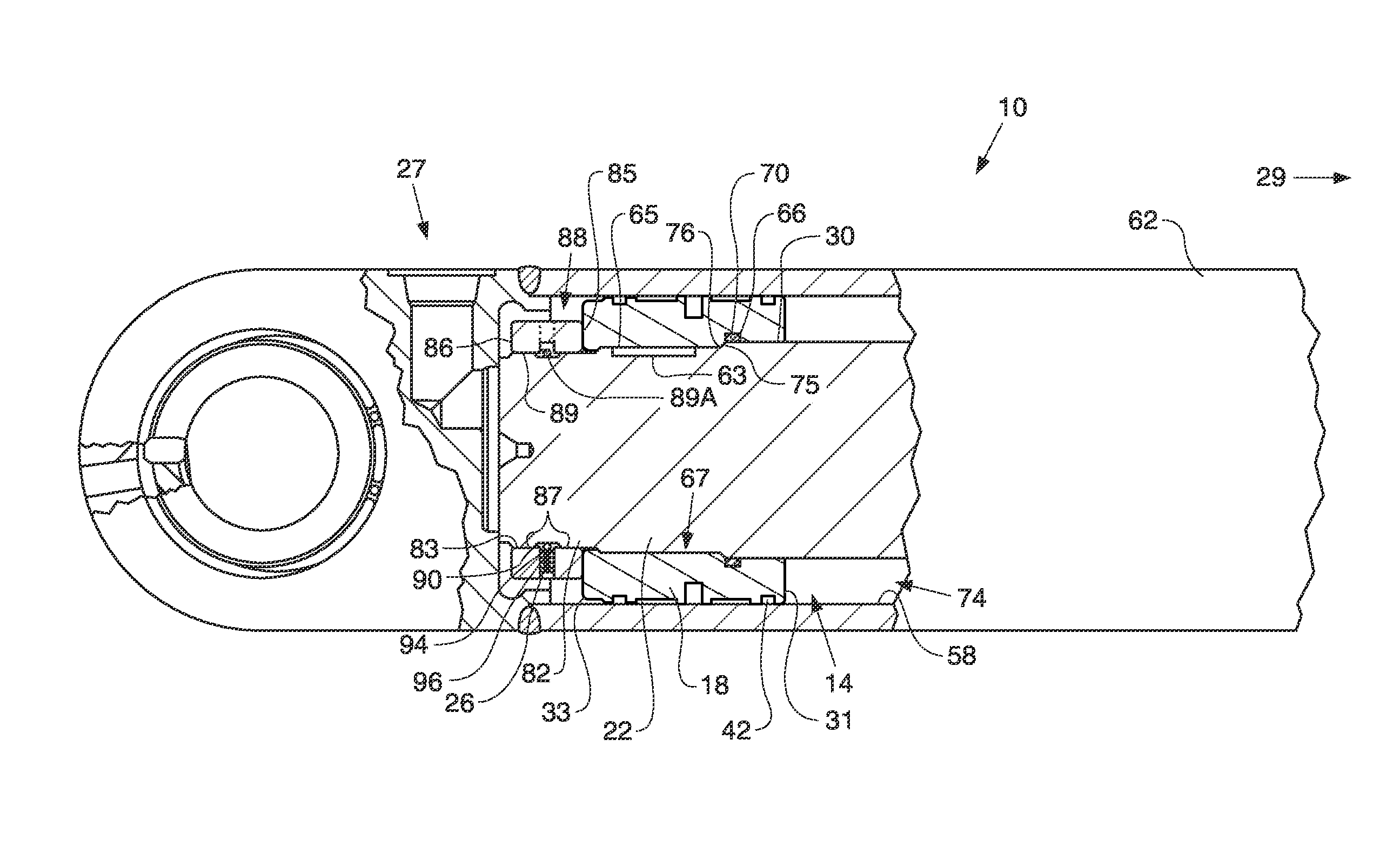
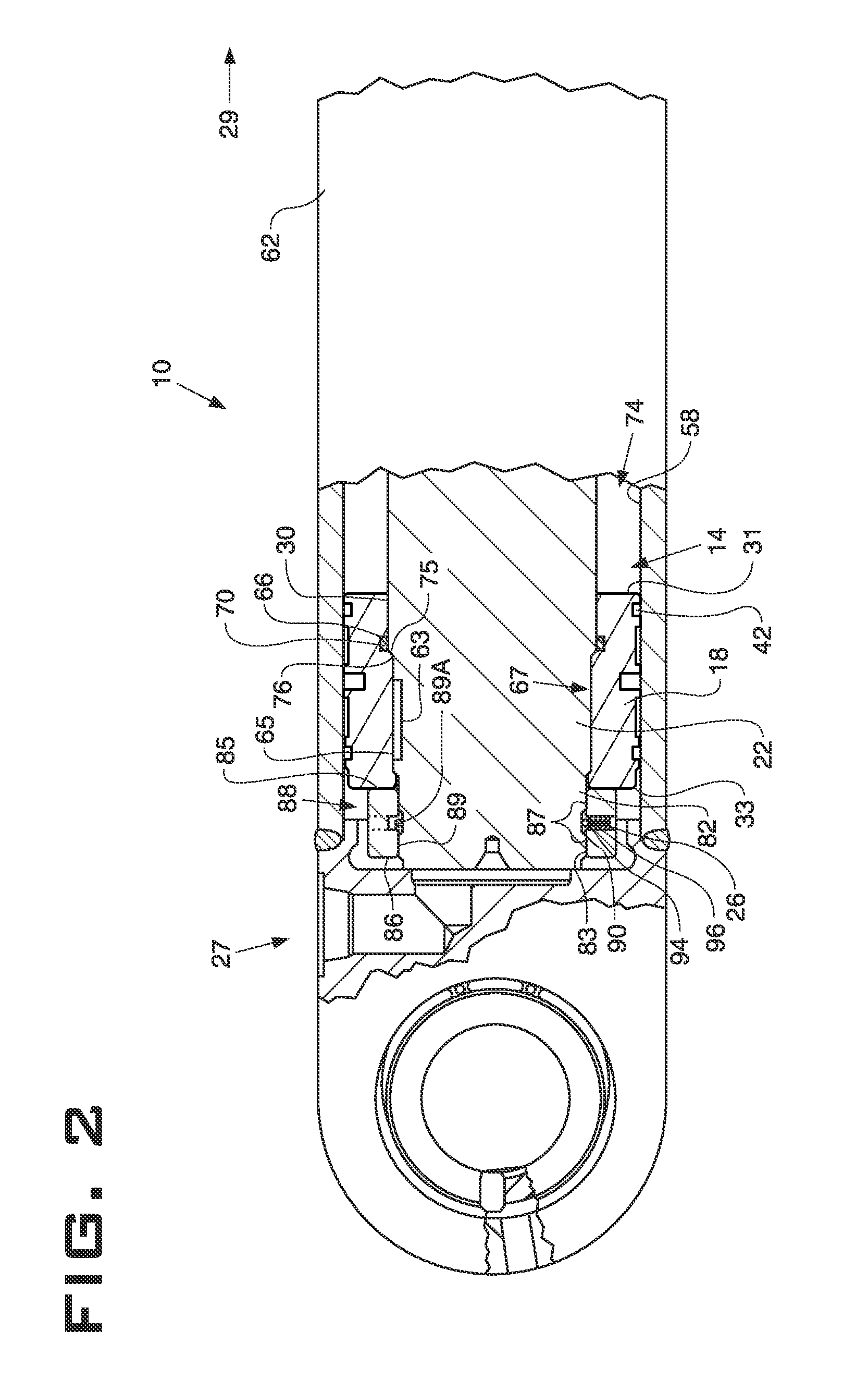
[0017]Referring to FIG. 2, a cylinder assembly 10 may include a piston and rod assembly 14. The piston and rod assembly 14 may include a piston member 18, a preferably cylindrical rod member 22, and a retaining member 26. The cylinder assembly 10 can have a head end 27 and a rod end, shown by the arrow 29.

[0018]The piston member 18 may be a ring shaped element having a piston bore 30 formed longitudinally therein extending between a first end 31 and a second end 33 of the piston member 18. The second end 33 may be closer to the head end 27 of the cylinder assembly than the first end 31. The piston bore 30 may be substantially cylindrical in shape and may extend entirely through the piston member 18. One or more outer seal groove...


PUM

PropertyMeasurementUnit
Torqueaaaaaaaaaa

Abstract

An apparatus and method for coupling a piston to a rod to form a cylinder assembly are provided. The piston has a tapped bore extending therethrough for coupling to a first threaded region of the rod. The rod end extends beyond the piston member and includes a second threaded region for coupling to a tapped bore of a retaining member. The piston member is coupled to the rod member at a low torque, e.g., up to about 1000 Nm. An external thread of each of the threaded segment of the piston bore and the first threaded region of the first portion of the rod member may be formed with a root radius of greater than 0.125 pitch or with MJ class thread. The retaining member may include setscrews offset from one another for frictional engagement with the rod end. The thread pitch between the rod and the piston may be coarser than between the rod and the retaining member. An interface and a seal region between the rod and the piston may be disposed closer to the rod end side of the piston member than the threaded coupling.

Description

RELATED APPLICATIONS[0001]This application is based upon and claims the benefit of priority from U.S. Provisional Application No. 61 / 604,710 by Dinesh Desai et al., filed Feb. 29, 2012, the contents of which are expressly incorporated herein by reference.TECHNICAL FIELD[0002]The present disclosure relates generally to a piston and rod assembly and more particularly to an apparatus and method for coupling together a piston and a rod.BACKGROUND[0003]Hydraulic cylinder arrangements typically include a piston member coupled to a rod member to form a piston and rod assembly. Various coupling arrangements have been used in the past to couple a piston member to a rod member.[0004]For example, in a standard piston and rod assembly, a rod member is provided having a threaded reduced-diameter end. A piston member is provided to be received over the rod member end and for slideable engagement with a non-threaded region adjacent to the rod member end. A piston nut can be threadably engaged with...

Claims


Application Information

Patent Timeline
IPC IPC(8): F16J1/00F16J1/08
CPCF16J1/005F16J1/08Y10T29/49256
Inventor DESAI, DINESHBUCKLEY, CHRISSYBRANDY, BRIAN
Owner CATERPILLAR INC
Why Eureka
Try Eureka