Splicing ring for tubular high-pressure fluid conduits

a technology of fluid conduit and splicing ring, which is applied in the direction of fluid pressure sealed joints, joints with sealing surfaces, sleeve/socket joints, etc., can solve the problems of limited security, excessive deterioration, and offer a total guarantee of stability, so as to avoid deterioration.

Active Publication Date: 2015-12-01
UNIONES APROL SA
View PDF13 Cites 0 Cited by
  • Summary
  • Abstract
  • Description
  • Claims
  • Application Information

AI Technical Summary

Benefits of technology

[0009]The splicing ring for tubular high-pressure fluid conduits, object of the present invention, offers an adequate solution to the drawbacks of known devices mentioned in the preceding paragraphs. Two metal rings having preformed edges are disposed underneath the inner metal band of the ring, which lock around the entire perimeter of both edges of the O-ring of the assembly, protecting said edges and avoiding deterioration thereof.
[0010]Likewise, the welded joint between the outer and inner metal rings will be enhanced thanks to elongated dies made in the outer band and there will be a greater line of contact between the two bands, as described below.
[0011]Therefore, the splicing ring object of this invention presents a double band divided into two halves, identical and joined together in their entirety, having the adequate thickness for their tightening function, being fully and perfectly adaptable, in a diametrical direction, to the outer perimeter of the tubular conduits to be spliced, whereupon sufficient pressure can be exerted along said perimeter to prevent any accidental movement of the ends of the tubular conduits due to the pressures that can originate in the splicing area.

Problems solved by technology

However, the ultimate aim of obtaining a fully hermetic joint is limited in terms of security due to the fact that the conduits can expand or contract due to temperature changes, particularly those conduits manufactured from polypropylene, which are highly sensitive to temperature changes.
The drawback of this embodiment is that the edges of the O-ring disposed beneath the rings are not sufficiently protected, which causes excessive deterioration, added to the fact that the weld points are limited and do not offer a total guarantee of stability and fixation of the outer rings over the inner rings.

Method used


Image

  • Splicing ring for tubular high-pressure fluid conduits
  • Splicing ring for tubular high-pressure fluid conduits

Examples


Embodiment Construction

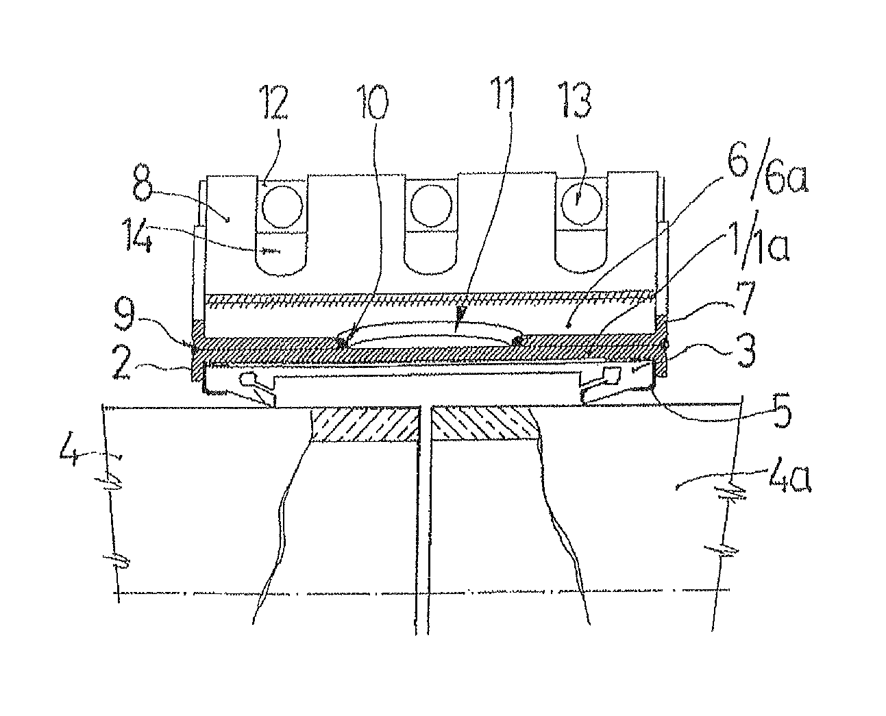
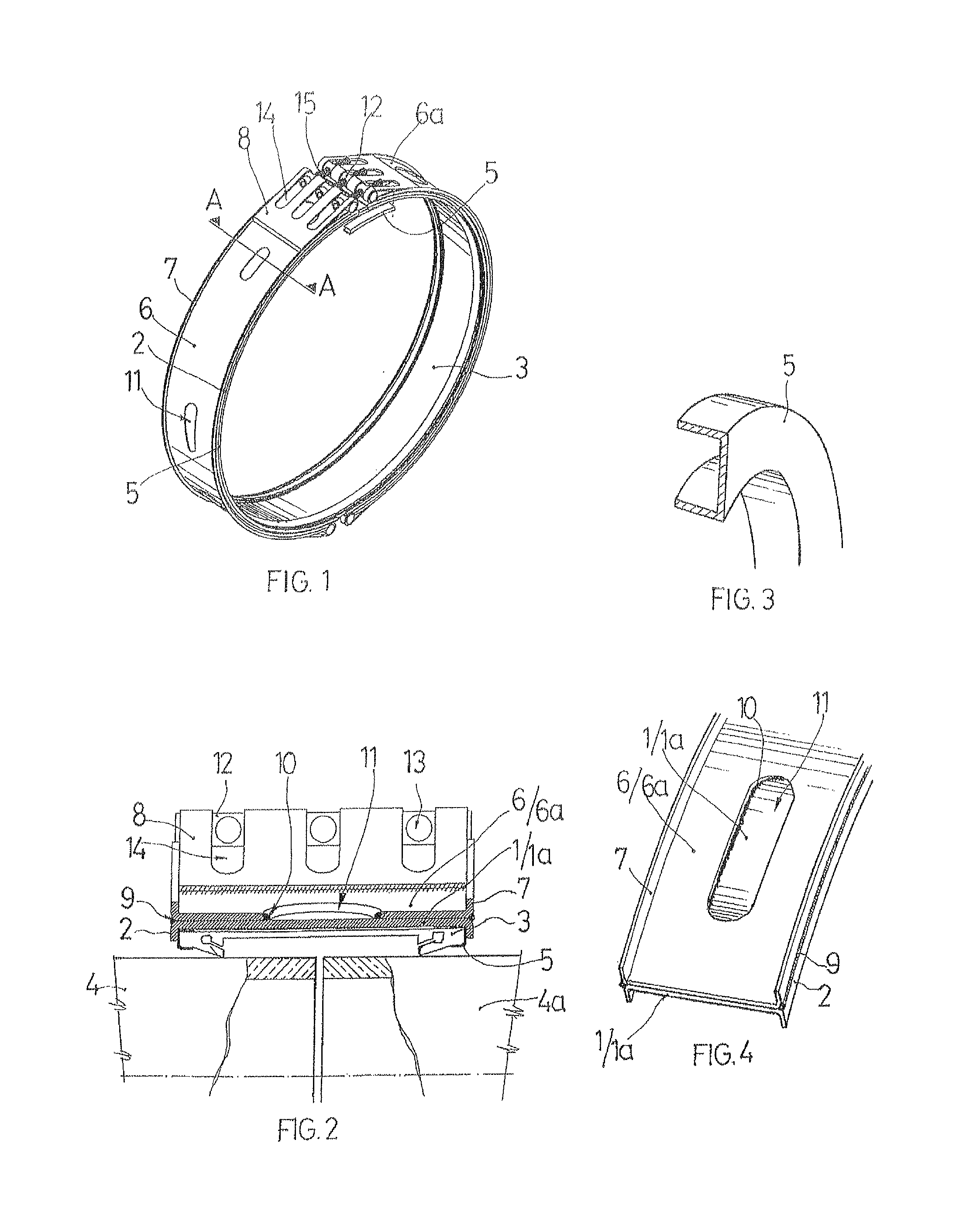
[0019]In accordance with the aforementioned drawings, the splicing ring for tubular conduits destined for conveying high-pressure fluids, liquids or gases, consists of a metal band, formed in the example represented by two independent and identical halves or bands —1— and —1a—, the side edges —2— of which are folded downwards in a right angle, constituting the edges that retain the relevant O-ring —3— in position. Said O-ring —3— has a known, characteristic and adequate profile for ensuring a hermetic seal in the splicing area of the two opposing tubular conduits —4— and —4a—.

[0020]The edges of the O-ring —3— are advantageously covered throughout their outer perimeter by two protective metal bands —5— preformed into a U shape to adapt and fully adjust to said perimeter edges of the O-ring —3—, offering full protection to the aforementioned edges and preventing deterioration thereof.

[0021]The splicing ring is completed by a second outer band, manufactured from the same material as t...


PUM


Abstract

A splicing ring for tubular high-pressure fluid conduits includes an inner metal ring formed of two independent and identical band halves having side edges. The side edges are folded downwards at a right angle and are configured as positioning and retaining elements of an O-ring. The O-ring rests upon the ends of the two tubular conduits to be spliced.

Description

CROSS REFERENCE TO RELATED APPLICATION[0001]The invention described and claimed hereinbelow is also described in Spanish patent application No. U201230038 filed on Jan. 16, 2012. This Spanish Patent Application, whose subject matter is incorporated here by reference, provides the basis for a claim of priority of invention under 35 U.S.C. 119 (a)-(d).BACKGROUND OF THE INVENTION[0002]The object of the present invention is a splicing ring destined for joining tubular conduits, generally cylindrical pipes used to convey high-pressure fluids, the essential characteristics of which are described below.[0003]Conveying high-pressure fluids by means of tubular conduits requires ensuring the maximum guarantee of safety at the splice points of one segment of the conduit to another. Although in these types of conduits segments of considerable length can be installed, obtained by joining, with adequate welds, various unit elements until reaching said lengths, for the purpose of reducing splices ...

Claims


Application Information

Patent Timeline
Patent Type & Authority Patents(United States)
IPC IPC(8): F16L17/04F16L21/06F16L21/02F16L19/04F16L17/03
CPCF16L19/046F16L17/032F16L21/06F16L21/022F16L17/04F16L21/02F16L21/065
Inventor PIRES CABADO, BARBARA INESPIRES CABADO, ELISABET PATRICIA
Owner UNIONES APROL SA
Why Eureka
Try Eureka