Set back box

a technology of set back boxes and boxes, which is applied in the field of set back boxes, can solve the problems of reducing the functionality generating strain on the cable, and reducing the size and volume of the electronics, so as to reduce damage, reduce the size of the set back box, and reduce the space

Inactive Publication Date: 2015-12-01
THOMSON LICENSING SA
View PDF22 Cites 1 Cited by
  • Summary
  • Abstract
  • Description
  • Claims
  • Application Information

AI Technical Summary

Benefits of technology

[0011]A set back box device which replaces the traditional visible rectangular set top box is provided. The device has all of the functionality of a traditional set top box, but has the advantages of being out of sight (i.e. can be hidden from view behind a television) and requires less space. The device can have printed circuit boards which are fragmented and stacked in a manner that permit the internal contents to be efficiently housed in a cylindrically shaped housing. The device is suspended behind a television by a working electrical cable that connects to the television and the device can have a strain relief cable to reduce damage due to cable pulling on the set back box.
[0015]Set back boxes of the invention can also be adapted to mount in a display or in a wall. For mounting in a display, the set back box can comprise a flange on the outer housing arranged such that the input side is exterior to the display and the input side is inside the display. For mounting in a wall, the set back box can comprise a flange on the outer housing arranged such that the input side is on an interior side of the wall and the output side is on the exterior side of the wall. These embodiments make the set back box easier to hide.

Problems solved by technology

Even though set back boxes have been configured to have minimal size and to not take up much surface area or volume in entertainment centers, such set back boxes are believed to generate strain on the cables.
Furthermore, while the size and volume of electronics have shrunk, their functionality has not, and, in fact, their functionality may be increasing with the need to interoperate on multiple networks simultaneously.
The wires that connect to set top box 1 in FIG. 1B can become an eye-sore.
Some have mounted set top boxes inside walls to hide the boxes from view; however, this is cumbersome and may not be encouraged in some households.
Some have attached the set back boxes to the backs of displays; however, this approach places displays at risk of damage, because robust adhesive used to facilitate proper mounting can spall the mounting surfaces.

Method used


Image

  • Set back box
  • Set back box
  • Set back box

Examples


Embodiment Construction

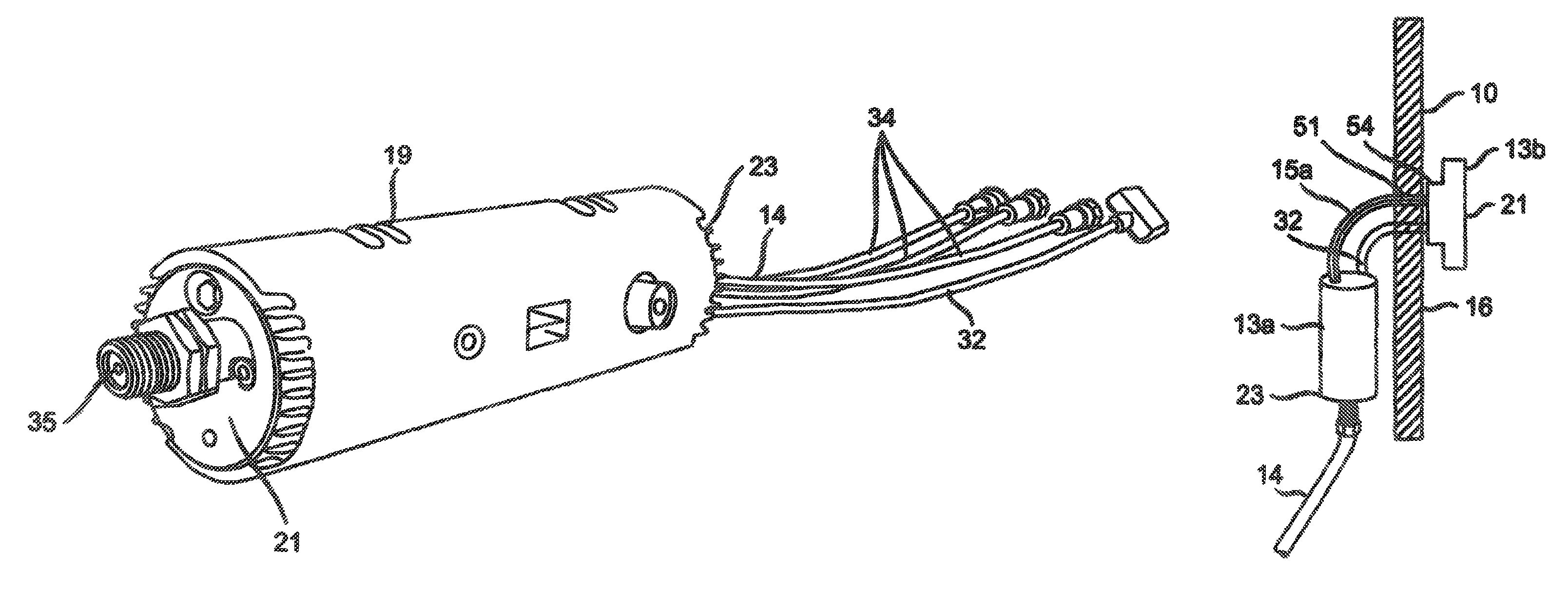
[0030]The set back box 13 which will now be described was developed to be a low cost device adapted to provide cable, satellite or hybrid whole home DVR (digital video recording) services when used in tandem with video gateways. The set back box 13 can also be adapted to receive and decode MPEG content and provide a flexible platform to support a wide range of applications for home networking architectures that can include various Ethernet and coaxial cable standards and WiFi.

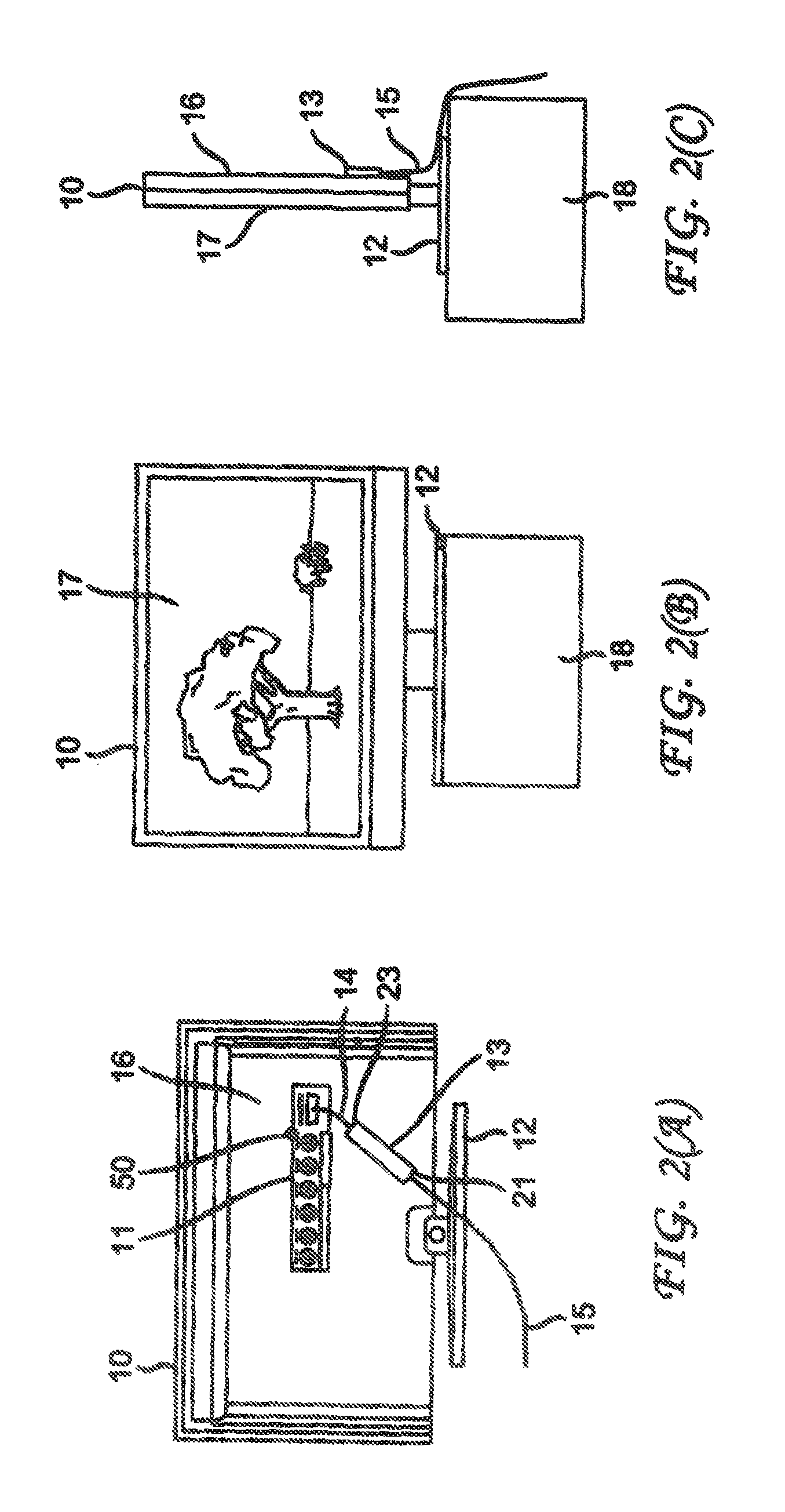
[0031]FIG. 2 shows various views of a display 10 employing the set back box 13 of the invention. FIG. 2A is a rear view of the display 10 supported by a base 12 in which the set back box 13 is shown being connected to at least one connector on the panel jack 11 through front cable 14 on the back 16 of the display 10. FIG. 2B shows the front 17 of the display 10 which demonstrates how the set back box is hidden from view and FIG. 2C shows a side view of the display 10 showing the rear cable 15 from which the set...


PUM


Abstract

A set back box is provided that comprises: an outer housing having one input side and one output side; stacked printed circuit boards within the outer housing; an input panel for receiving at least one input electrical cable at the one input side; and an output panel for providing signal to a display through at least one output cable at the output side. A strain relief cable is also provided that connects to the output side, wherein the strain relief cable is configured to attach to the display and configured to ensure any output cables are not under tension.

Description

CROSS-REFERENCE TO RELATED APPLICATIONS[0001]This application is a National Stage Application and claims the benefit, under 35 U.S.C. §365 of International Application PCT / US2012 / 020013 filed Jan. 3, 2012 which was published in accordance with PCT Article 21(2) on Jul. 12, 2012 in English and which claims the benefit of U.S. Provisional Patent Application No. 61 / 429,639 filed Jan. 4, 2011 and U.S. Provisional Patent Application No. 61 / 465,786 filed Mar. 24, 2011.FIELD OF THE INVENTION[0002]The invention is related to set back boxes and mounting of set back boxes.BACKGROUND OF THE INVENTION[0003]An increasing number of consumers prefer to reduce the visibility of set top boxes. In response, an effort to eliminate set top boxes from view has been undertaken which includes the development of set back boxes. These set back boxes perform the traditional functions of a set top box, but are generally hidden from the field of view.[0004]In one configuration the set back boxes are designed t...

Claims


Application Information

Patent Timeline
Patent Type & Authority Patents(United States)
IPC IPC(8): H04N5/64
CPCH04N5/64
Inventor GYSIN, MARK WILLIAMRUCH, GLEN WAKEMAN
Owner THOMSON LICENSING SA
Why Eureka
Try Eureka