Detachable cutting assembly

a cutting assembly and detachable technology, applied in the direction of metal working equipment, etc., can solve the problems of reducing cutting time and cutting efficiency loss

Active Publication Date: 2022-06-30
SAMMIC
View PDF4 Cites 0 Cited by
  • Summary
  • Abstract
  • Description
  • Claims
  • Application Information

AI Technical Summary

Benefits of technology

[0011]Due to this configuration, the removable cutting assembly provides greater versatility for its use, using flaps with lifting wedges of different heights and these can be easily replaced by the user using common tools in professional kitchens. In this manner, slices of food of different thicknesses are obtained, adapting to the needs of the user. Moreover, cleaning is facilitated, since the flap in which the blade is partially embedded is removable, this being a fundamental requirement in the field of food product production and guaranteeing food safety. In addition, the fact that the nuts are embedded in the fixing area of the flap means that the exchange and / or replacement of the flap by kitchen personnel will be much simpler, since they must attend to the extraction of the connecting elements, screws, without worrying about removing the nuts to disassemble the assembly. With this linking configuration of the elements, in which the containing flap of the cutting blade is partially inserted in the lower face of the rotating disc and partially protruding on the upper face of the disc, a better fixation of the cutting element—blade—of the flap is achieved, as it is trapped and its movement limited not only by the linking elements, but also by the entire surface of the fixing area of the rotating disc. In addition, by foreseeing that the lifting wedge is manufactured by plastic injection on the blade and the nuts, the possibility of accumulation of food residues is eliminated, thus eliminating the possible contamination of the food and reducing their cutting time, since an accumulation of residues causes a loss of cutting efficiency. Furthermore, when the user requires the use of different flaps to obtain different slice thicknesses, he will only have to modify, at the time of manufacture, the dimensions of the plastic flap, the blade having the same dimensions for all slice thicknesses. This entails a significant reduction in manufacturing costs since the flap injection material is plastic, which is significantly cheaper than steel, which is the usual raw material from which the blade is manufactured. Another advantageous aspect of this configuration is that the elevation of the cutting edge of the blade projecting over the upper face of the rotating disc is determined by the height of the lifting wedge of the flap and the angle of incline thereof (between 21° and 23°), achieving an incline as smooth and minimal as possible, optimizing the cutting of the food slices, without spoiling or damaging the product and avoiding breakage in the fibre of delicate foods, such as tomatoes or similar, and, in this manner, the desired thickness cut can be performed without damaging them, the final appearance of the product being crucial in professional kitchens.
[0012]Another technical aspect of the present invention is that the window of the rotating disc has a dimension and geometry corresponding to the dimension and geometry of the lifting wedge of the flap. Due to this characteristic, the lifting wedge of the flap is perfectly inserted into the rotating disc, being efficiently housed and allowing the edge of the blade to protrude from the upper face of the disc, thus achieving an efficient cutting of the food slices without these being damaged, as well as a greater adjustment and fixation of the blade, its movements or vibrations being limited by the coupling with the window in almost the entire perimeter of the lifting wedge.
[0013]Another advantageous characteristic of the present invention is that, on the area of attachment of the rotating disc and attached to the lifting wedge, a security component is incorporated consisting of at least one mooring hole coincident with at least one mounting hole of the rotating disc and at least one tie-down hole, and one wing nut. Thanks to the introduction of the safety component attached along the opposite side to the blade of the lifting wedge, a distribution of forces is produced ensuring the fixation of both the blade and the flap to the rotating disc and increasing the integrity of the fixation. In addition, by using this safety component, there is a reduction in the damaging vibrations caused by the striking of the food against the blade during the cutting process, which weaken the adjustment of the fixings, thus achieving the homogenization of the thickness in the food slices, their integrity and a homogeneous appearance therebetween.
[0014]Lastly, another advantageous aspect of the present invention is that the profile of the rotating disc may contain a levelling platform in the fixing area and the perimeter of the pivot hole of the rotating disc levelling the rising portion of the cutting edge of the blade on the upper face of the rotating disc. With the presence of this platform, which must be located on the lower face of the disc, a greater range of thickness of food slices can be achieved with the use of a smaller number of lifting wedges, thereby providing the present invention with greater versatility. For example, with wedge angles of 21° and 23° and heights of 1 mm, 2 mm and 3 mm, up to 6 different slice thicknesses can be achieved. With said platform in the disc profile, a projection or protrusion is generated on the underside of the rotating disc, the side on which the lifting wedge containing the cutting blade is inserted, which means reducing the height of the inserted lifting wedge. Thus, when incorporating, for example, a lifting wedge with a height of 2 mm that would allow slices of 2 mm to be obtained when using a rotating disc without a levelling platform, or slices of 5 mm would be obtained if we use a rotating disc with a levelling platform of 3 mm.

Problems solved by technology

In addition, by foreseeing that the lifting wedge is manufactured by plastic injection on the blade and the nuts, the possibility of accumulation of food residues is eliminated, thus eliminating the possible contamination of the food and reducing their cutting time, since an accumulation of residues causes a loss of cutting efficiency.

Method used


Image

  • Detachable cutting assembly
  • Detachable cutting assembly
  • Detachable cutting assembly

Examples


Embodiment Construction

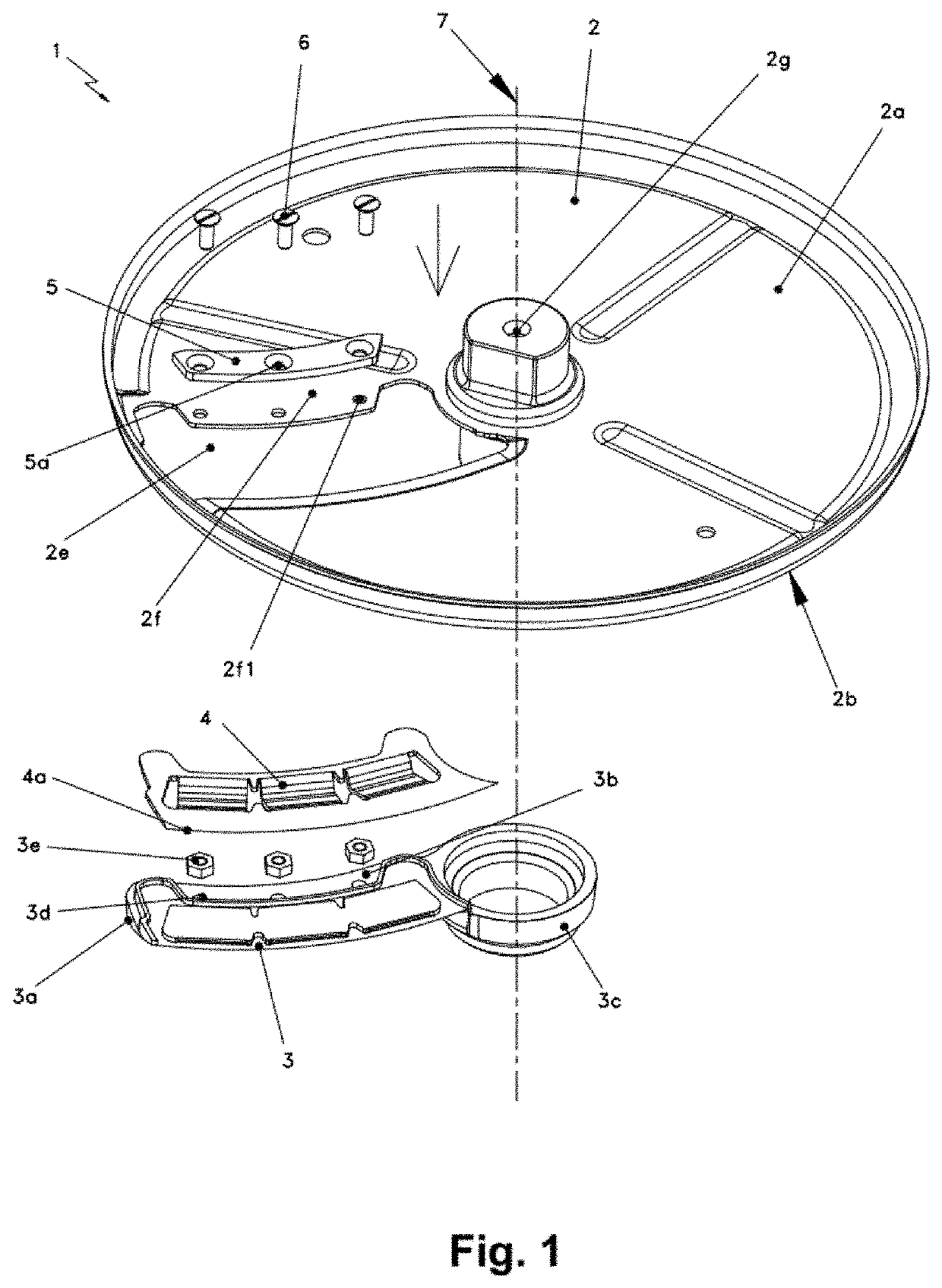
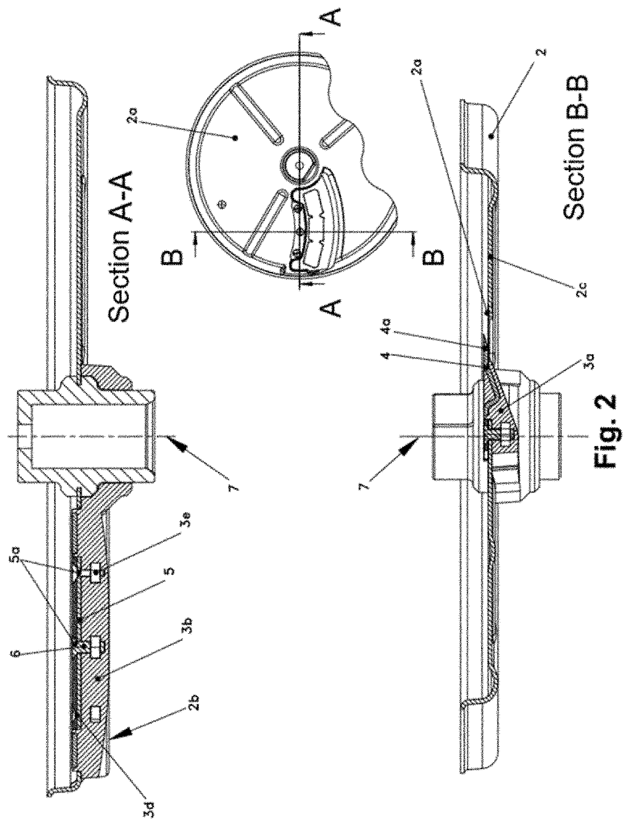
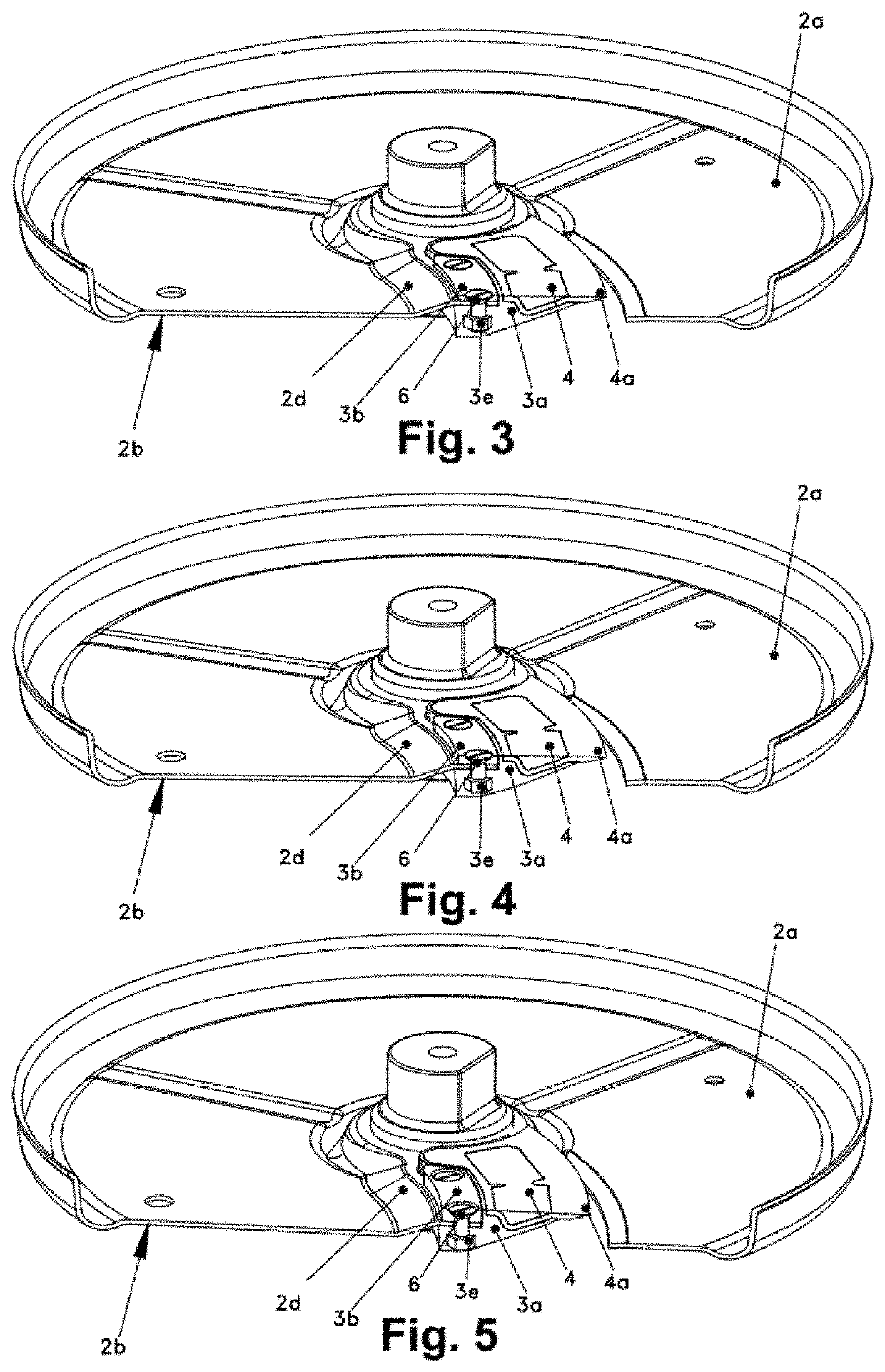
[0044]With regard to the above-listed drawings and references, a preferred mode of execution of the object of the invention is illustrated in the attached drawings referring to an improved removable cutting assembly (1) used in food cutting machines that consists of a rotating disc (2) with a window (2e) and a pivot hole (2g) linked to the rotation axis of the cutting machine (7), to which a flap (3) connected radially to the rotation axis of the cutting machine (7) by means of its insert ring (3c) in which the flap (3) consists of; a fixing area (3b) in which at least one nut (3e) is embedded and on which there is at least one fastening hole (3d) coinciding with at least one nut (3e), and a lifting wedge (3a) on which a blade (4) is partially embedded, leaving the cutting edge (4a) of the blade (4) protruding on the upper face (2a) of the rotating disc (2) through the window (2e) of the rotating disc (2), and the fixing area (3b) of the flap (3) being below the fixing area (2f) of ...


PUM


Abstract

The improved detachable cutting assembly used in food cutting machines includes a rotating disc with a window and a pivot hole linked to the rotation axis of the cutting machine. A flap is connected radially to the rotation axis of the cutting machine by its insert ring. The insert ring includes a fixing area in which at least one nut is embedded and on which there is at least one fastening hole coinciding with at least one nut, and a lifting wedge on which a blade is partially embedded, leaving the cutting edge of the blade protruding on the upper face of the rotating disc through the window of the rotating disc. Existing in the fixing area of the rotating disc, there is at least one fastening hole coinciding with the fastening hole and the nut of the flap and capable of fixing the whole assembly by linking elements.

Description

CROSS-REFERENCE TO RELATED APPLICATIONS[0001]See Application Data Sheet.STATEMENT REGARDING FEDERALLY SPONSORED RESEARCH OR DEVELOPMENT[0002]Not applicable.THE NAMES OF PARTIES TO A JOINT RESEARCH AGREEMENT[0003]Not applicable.INCORPORATION-BY-REFERENCE OF MATERIAL SUBMITTED ON A COMPACT DISC OR AS A TEXT FILE VIA THE OFFICE ELECTRONIC FILING SYSTEM (EFS-WEB)[0004]Not applicable.STATEMENT REGARDING PRIOR DISCLOSURES BY THE INVENTOR OR A JOINT INVENTOR[0005]Not applicable.BACKGROUND OF THE INVENTION1. Field of the Invention[0006]This invention concerns an improved detachable cutting assembly. More specifically, it refers to an improved detachable cutting assembly used in food cutting machines in professional kitchens, structured on the basis of a rotating disc consisting of a window and a pivot hole linked to the rotation axis of the cutting machine, to which a flap containing the cutting blade is inserted into the lower face of the rotating disc, linked to the rotation axis of the c...

Claims


Application Information

Patent Timeline
Patent Type & Authority Applications(United States)
IPC IPC(8): B26D7/26B26D1/143
CPCB26D7/2635B26D2001/0046B26D2210/02B26D1/143
Inventor LIZARAZU GONZALEZ, TOMASAGUIRREZABALAGA, AITOR
Owner SAMMIC
Why Eureka
Try Eureka