Optical disc reproduction apparatus

a technology of optical discs and reproduction apparatuses, which is applied in the direction of electric apparatus casings/cabinets/drawers, instruments, carrier covers, etc., can solve the problems of increasing the production cost of the whole apparatus, and increasing the size of the main body, so as to improve the portability of the apparatus, efficient housing in the main body, and reducing the effect of the production cos

Inactive Publication Date: 2013-06-04
FUNAI ELECTRIC CO LTD
View PDF14 Cites 0 Cited by
  • Summary
  • Abstract
  • Description
  • Claims
  • Application Information

AI Technical Summary

Benefits of technology

[0009]The present invention is to solve the problem described above, and an object of the present invention is to provide an optical disc reproduction apparatus which can efficiently house a two-axis hinge and a battery pack in a main body to make the apparatus smaller and thinner even though the two-axis hinge is located in a center of a back end of the main body, so that portability of the apparatus can be improved, and moreover, a rise in production cost of the whole apparatus can be prevented.
[0015]According to the above configuration, the recess in the battery pack is located in a position corresponding to the hinge mounting-housing portion in the main body, and has the width larger than that of the hinge mounting-housing portion in the rightward-leftward direction, and moreover, the housing recess which houses the battery housing of the battery pack on right and left sides of the hinge mounting-housing portion on the back end of the main body. Thus, the two-axis hinge and the battery pack attached to the center of the back end of the main body can be housed in the main body efficiently, and the apparatus can be made smaller and thinner. As a result, portability of the apparatus can be improved. Moreover, in contrast to the case that the battery packs are separately provided on the both sides of the main body so that the hinge is located between the battery packs as described in claim 2 of Japanese Laid-Open Patent Publication No. 11-134065, the circuit board for charging and discharging the plural cylindrical secondary batteries in the battery pack can be commonalized, and the rise in the production cost of the whole apparatus can be prevented. Furthermore, the housing recesses are provided on the right and left sides of the hinge mounting-housing portion in the back end of the main body to house the battery housings in the battery pack, so that a weight of the whole apparatus can be well-balanced.
[0016]It is preferable that the battery pack has two battery housings in total on its both ends in a longitudinal direction, and the battery housings house plural cylindrical secondary batteries, respectively. According to the above configuration, the apparatus can be made thinner without using an expensive prismatic secondary battery, so that the rise in the production cost of the whole apparatus can be prevented.
[0017]It is more preferable that the battery pack has a circuit board for charging and discharging all the cylindrical secondary batteries housed in the two battery housings in common in the recess. According to the above configuration, the rise in the production cost of the whole apparatus can be reliably prevented.
[0018]It is preferable that the housing recess in the main body has a guide bar to attach the battery pack, a longitudinal direction of the guide bar is a direction parallel to a horizontal surface when putting the main body on the horizontal surface, the battery pack has a guide groove into which the guide bar can be inserted, and upper surfaces of the battery housings in the battery pack are flat and parallel to a longitudinal direction of the guide groove. According to the above configuration, when the battery pack is attached to and detached from the main body while putting the main body on the horizontal surface, the longitudinal direction of the guide bar provided on the housing recess in the main body, the longitudinal direction of the guide groove provided in the battery pack, and the upper surfaces of the battery housings in the battery pack are parallel to the horizontal surface, so that in contrast to the invention described in the above Japan Patent No. 3407990, the battery pack can be easily attached to and detached from the main body in the horizontal direction.

Problems solved by technology

Although the above apparatus which uses the prismatic secondary battery as the secondary battery in the battery pack can be thin, the prismatic secondary battery is more expensive than a cylindrical secondary battery, so that a production cost of the whole apparatus rises.
When the battery pack is separated into at least two parts, it is impossible to commonalize a circuit board for charging and discharging the plural secondary batteries in the battery pack, so that a production cost of the whole apparatus rises.
Furthermore, as for the apparatus in which the battery pack is connected to the back end of the main body as shown in Registered Utility Model No. 3025417 and Japanese Laid-Open Patent Publication No. 8-76898, the main body is large in a front / back width, so that the main body gets larger and such an apparatus lacks portability.
However, this type of apparatus can be reduced in thickness for only a part of a diameter of the pivoting axis of the hinge mechanism at most, so that it is possible to reduce a thickness of a portable information processing apparatus provided with the one-axis hinge in which a part of pivoting axis of the hinge mechanism forms a hinge joint member to the main body, however, it is not possible to reduce a thickness of the apparatus provided with the two-axis hinge in which the hinge joint member to the main body is formed separately from the part of the hinge mechanism.
Moreover, in this apparatus, the part of pivoting axis of the hinge mechanism is stored in the recess of the battery pack when attaching the battery pack to the main body, so that the battery pack cannot be attached to and detached from the main body in the horizontal direction.

Method used


Image

  • Optical disc reproduction apparatus
  • Optical disc reproduction apparatus
  • Optical disc reproduction apparatus

Examples


Embodiment Construction

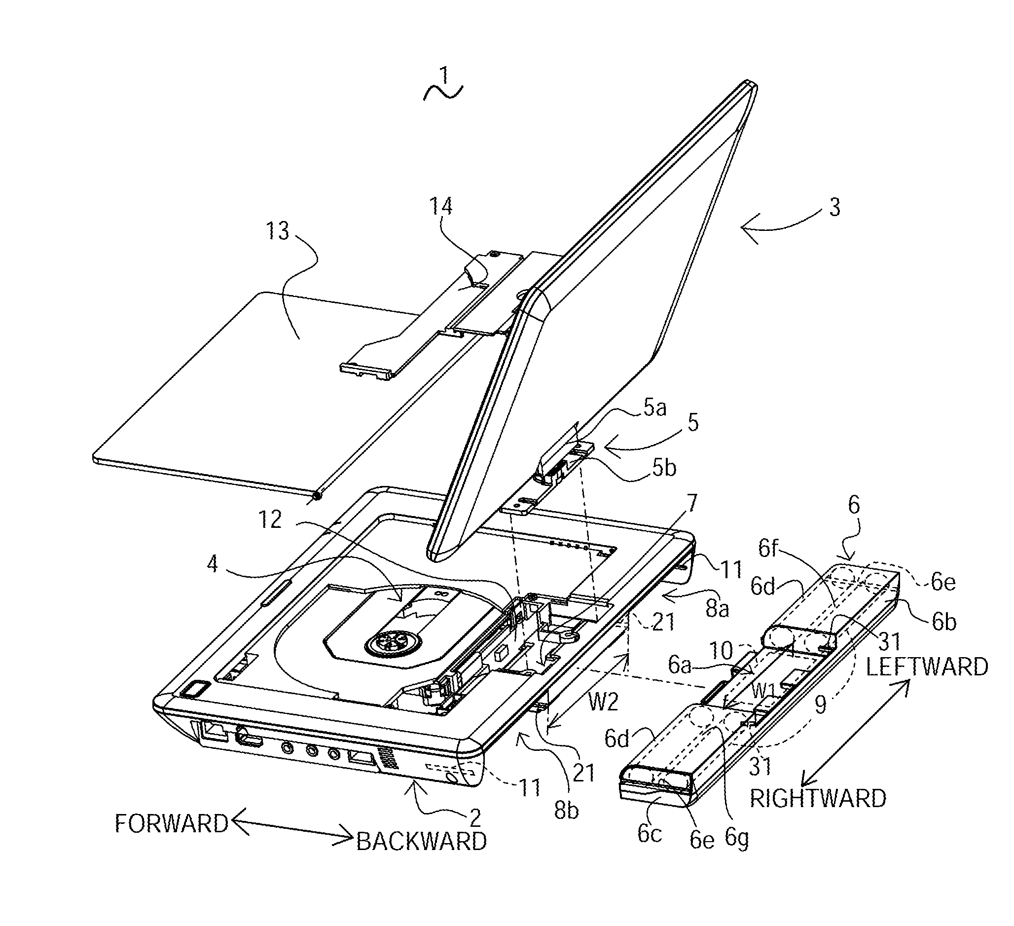
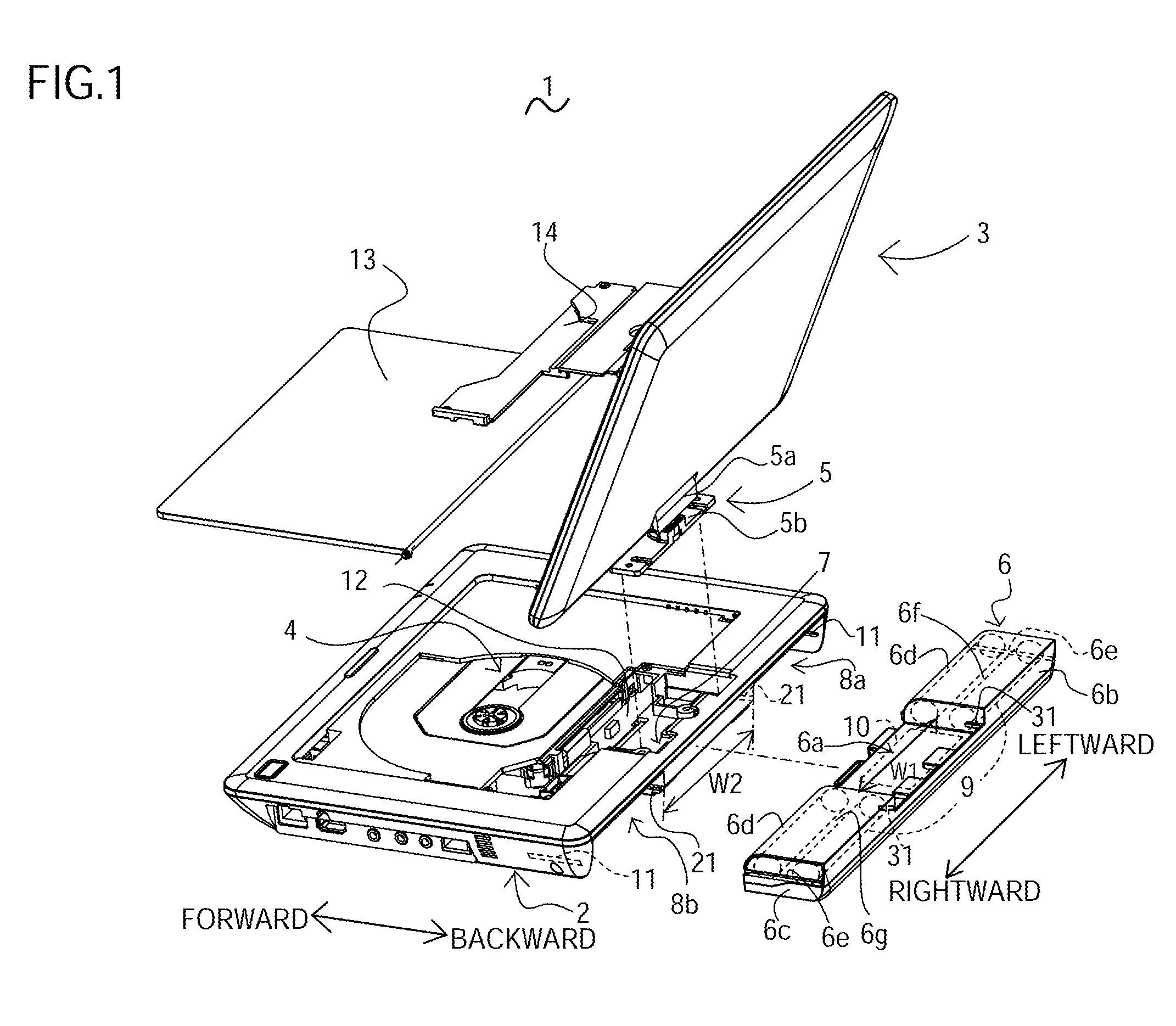
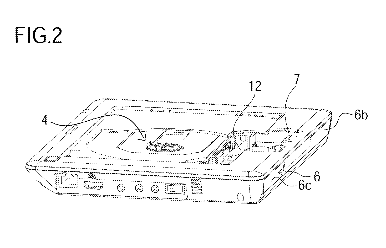
[0022]A preferred embodiment of the present invention is described with reference to FIGS. 1 and 2. FIG. 1 is an exploded perspective view of an optical disc reproduction apparatus according to the present preferred embodiment. In the following description and claims, a forward (direction), a backward (direction), a rightward (direction), and a leftward (direction) correspond to forward-backward and rightward-leftward directions indicated by arrows in FIG. 1, respectively. An optical disc reproduction apparatus 1 is made up of a main body 2 which has an optical disc reproduction unit 4 to reproduce an image recorded in an optical disc such as a blu-ray disc, a control board 12 to control the whole apparatus, and a liquid crystal display unit 3 (the display unit in claim) to display an image reproduced by the optical disc reproduction unit 4. The main body 2 and the liquid crystal display unit 3 is rotatably and pivotally connected to each other by a two-axis hinge 5, that is, the li...


PUM


Abstract

An optical disc reproduction apparatus includes a main body, a display unit, a two-axis hinge, and a battery pack. The two-axis hinge has a joint member to connect the two-axis hinge to the main body. The main body has not only a hinge mounting-housing portion to attach and house the joint member of the two-axis hinge but also a housing recess to house a battery housing of the battery pack on right and left sides of the hinge mounting-housing portion on a back end. The battery pack has a U-shaped recess in a center. The recess is located in a position corresponding to the hinge mounting-housing portion in the main body and has a width larger than that of the hinge mounting-housing portion in a rightward-leftward direction.

Description

BACKGROUND OF THE INVENTION[0001]1. Field of the Invention[0002]The present invention relates to an optical disc reproduction apparatus which reproduces an image recorded in an optical disc such as blu-ray disc and DVD (Digital Versatile Disc), for example.[0003]2. Description of the Related Art[0004]Recently, in a field of a portable optical disc reproduction apparatus, there is a known optical disc reproduction apparatus which includes a main body having an optical disc reproduction unit and a liquid crystal display unit for displaying an image reproduced by the optical disc reproduction unit, and the main body and the liquid crystal display unit is rotatably and pivotally connected by a two-axis hinge, that is, the liquid crystal display unit can rotate, open, and close with respect to the main body. Here, “rotation (rotatably)” means horizontal rotation of the liquid crystal display unit, and “pivoting (pivotally)” means back and forth rotation of the liquid crystal display unit...

Claims


Application Information

Patent Timeline
Patent Type & Authority Patents(United States)
IPC IPC(8): H05K5/00H05K7/00
CPCG06F1/1635G06F1/1681G11B33/025G11B33/027G11B33/12
Inventor MIYAGI, JUNJIKUME, HIDEKIMUROI, MARIYAMAMOTO, TAKAYUKI
Owner FUNAI ELECTRIC CO LTD
Why Eureka
Try Eureka