Eureka AIR delivers breakthrough ideas for toughest innovation challenges, trusted by R&D personnel around the world.

Nasal cavity dilator device

a dilator and nasal cavity technology, applied in the field of nasal cavity dilators, can solve the problems of increasing cardiac arrest risks, high cost, chronic addiction problems or withdrawal difficulties, etc., and achieve the effect of improving the passage of air

Inactive Publication Date: 2015-12-08
ASAP BREATHEASSIST
View PDF20 Cites 0 Cited by
  • Summary
  • Abstract
  • Description
  • Claims
  • Application Information

AI Technical Summary

Benefits of technology

This patent is about a nasal cavity device that can be used to smell air or medicine. The device includes a central platform that forms a roof enclosure for the device, providing a support surface for the device. The device also has a flexible wall structure made up of aligned ribs that can deform laterally when exposed to an external force, causing the device to push against the nasal cavity walls to improve airflow. The device can also be used with medicament or fragrance holders to provide a more pleasant or beneficial experience when breathing in the air. The technical effect of this device is to provide a more effective and pleasant way to breathe in air and other substances through the nasal passage.

Problems solved by technology

People who are disposed to such conditions can be subject to feelings of general tiredness, shortness of breath, fatigue, sleep deprivation, snoring, and even sleep apnoea, which can increase the risks of cardiac arrest.
Apart from requiring a sufferer to endure invasive surgery and the relatively high costs associated therewith, it is documented that surgical procedures are often temporarily successful, sufferers requiring repeated surgery to obtain ongoing relief.
One problem with ˜pray formulations, however, is that they often contain steroidal or vasoconstrictor active agents that cause side effects and can lead to a chronic addiction problem or withdrawal difficulties.
A further problem with spray formulations is that frequent dosing is required.
These types of devices involve complex designs that are very conspicuous on a wearer.
A problem associated with this type of approach is that the plaster is not aesthetically pleasing, and is limited by both the inherent resiliency of the plaster and its ability to exert a sufficient outward force to expand and maintain a nostril cavity in an open condition.
In addition the plaster requires painful removal that could result in the tearing of skin.
Also problems frequently arise in a nasal application when a wearer exhibits a deviated septum.
A curved septum often renders one nasal cavity a different shape and size to its neighbour and inhibits airflow through one side of the nose and can result in airflow blockage through one nostril.
Prior art devices, of the type disclosed in U.S. Pat. No. 5,895,409 that are insertable within the nasal cavity, suffer the drawback that if one dilator of a symmetrical pair, to be inserted, is of a sufficiently small size to enter one nostril then the remaining dilator of the pair is too small to be effective in dilating the other nostril.
Conversely, if one device of a symmetrical pair is sufficiently large to effectively dilate one nostril, its pair is often too large to be inserted in the other nostril.
Even further, the device of U.S. Pat. No. 5,895,409 cannot be used to deliver a medicament.
This device confers a deal of discomfort for a wearer upon insertion because the device is generally larger than the corresponding orifice in which it is to be inserted.
These type of dilators are very uncomfortable for a wearer and the force generated by the resilient plastic often causes irritation to the inside lining of the nose not to mention that the article is conspicuous.
To date no device or system has been provided which is capable of combining improved flow of air and delivering a medicament or fragrance or like material.
This is likely because of the size constraints within the nasal cavity of a human.
Even further, general breathing problems can be initiated upon exposure to dusts, pollens, and pollution.
Wearing of masks however is unsightly and significantly restricts flow of air into the nasal cavity.

Method used


Image

  • Nasal cavity dilator device
  • Nasal cavity dilator device
  • Nasal cavity dilator device

Examples


Embodiment Construction

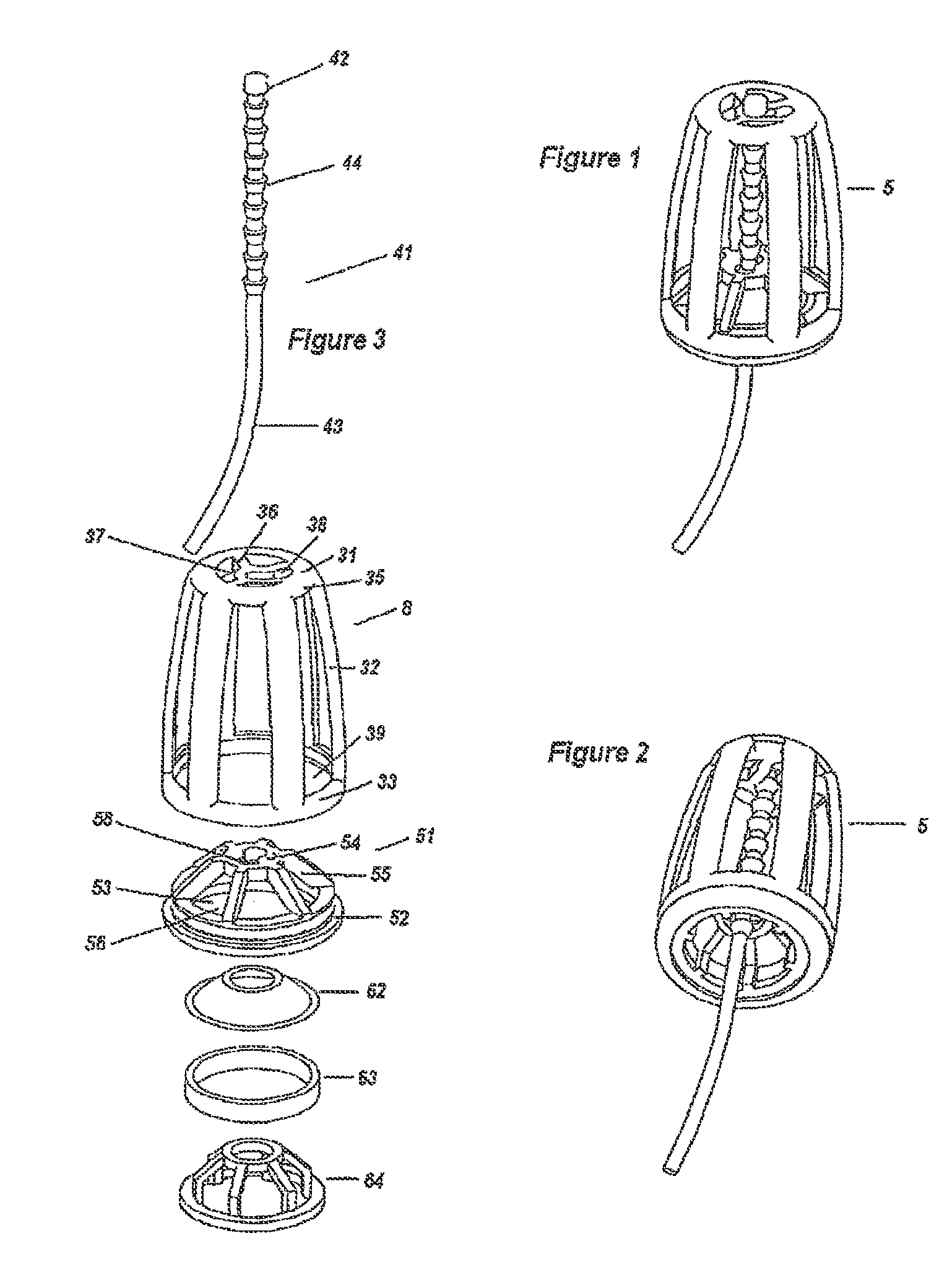
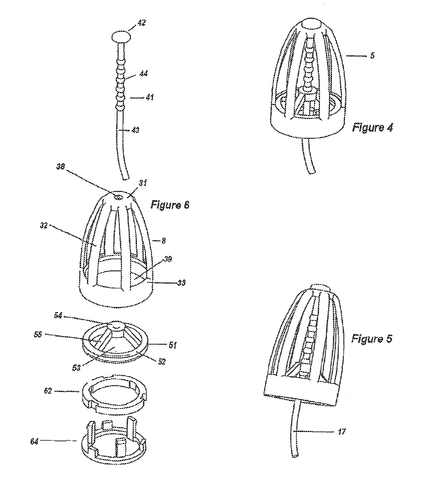
[0177]Referring to FIGS. 1 to 5 there is shown an improved adjustable nasal dilator device (1) insertable within the nasal cavity of a human being to improve the flow of air through the nasal passage. The device includes a body (2) comprising a top (3) and bottom (4) frame ends interconnected by a series of spaced flexible ribs (5). The top and bottom frame ends are open and substantially circular, and the diameter of the bottom frame end is greater than the corresponding diameter of the top frame end to provide a body shape for convenient insertion within a nasal cavity.

[0178]The device (1) also includes a holding base member (6). As best seen in FIG. 2, the holding base member mounts the bottom frame end (4) of the body (2). The holding base member includes an inner circumferential platform (7) for supporting the bottom frame end (4) of the body (2) in a mounting position. The holding base member also includes an outer concentric circumferential platform (8) for mounting outer she...


PUM


Abstract

An improved adjustable nasal dilator device insertable within the nasal cavity of a human being to improve the flow of air through the nasal passage. The device includes a body, a top and bottom frame ends interconnected by a series of spaced flexible ribs. The top and bottom frame ends are open and substantially circular, and the diameter of the bottom frame end is greater than the corresponding diameter of the top frame end to provide a body shape for convenient insertion within a nasal cavity.

Description

[0001]This application is a continuation of U.S. Ser. No. 12 / 154,868, filed May 28, 2008, claiming priority of Australian Application No. 2007202425, filed May 28, 2007 and a continuation-in-part of U.S. Ser. No. 11 / 363,884, filed Feb. 28, 2006, now U.S. Pat. No. 7,740,643, issued Jun. 22, 2010, a continuation of U.S. Ser. No. 10 / 631,415, filed Jul. 30, 2003, now U.S. Pat. No. 7,105,008, issued Sep. 12, 2006, a continuation-in-part of PCT International Patent Application No. PCT / AU2003 / 00504, filed Apr. 30, 2003, claiming priority of Australian Provisional Application Nos. 2003900315, filed Jan. 24, 2003, and 2002951517, filed Sep. 18, 2002, the entire contents of each of which are hereby incorporated herein by reference.FIELD OF THE INVENTION[0002]The present invention relates to an improved nasal cavity device for use in the nasal cavity of a human being to aid passage of air through the nasal cavity. More particularly the present invention relates to an improved adjustable nasal ...

Claims


Application Information

Patent Timeline
Patent Type & Authority Patents(United States)
IPC IPC(8): A61F2/18A61F5/56A61M15/08A61B17/24A61F5/08A61M29/00
CPCA61M29/00A61B17/24A61F5/08A61F5/56A61M15/085A61B2017/248A61M15/08
Inventor MARYANKA, PAZ
Owner ASAP BREATHEASSIST
Why Eureka
Eureka Blog
Learn More