Fuel Cell Separator, Electrode Structure for a Fuel Cell, Methods of Manufacturing Both Thereof, and a Polymer Electrolyte Fuel Cell Comprising the Same

a fuel cell and separator technology, applied in the direction of cell components, final product manufacturing, sustainable manufacturing/processing, etc., can solve the problems of inability to ensure the supply of gas below the ribs, small degree of freedom in the shape of the channel, and increase the degree of freedom of design of the gas channel structure, so as to reduce the contact resistance between the separator and the gdl. , the effect of reducing the degree of freedom

Active Publication Date: 2009-02-12
HORI MASARU +2
View PDF3 Cites 6 Cited by
  • Summary
  • Abstract
  • Description
  • Claims
  • Application Information

AI Technical Summary

Benefits of technology

[0023]In accordance with the invention, it becomes possible to use in a fuel cell electrode a carbon nanomaterial with a nanostructure such that microstructures, such as porosity, and macrostructures, such as patterns, can be freely modified. The invention also makes it possible to form the gas channel ribs and the diffusion layer in an integral manner. As a result, the following advantages can be obtained: (1) The degree of freedom of designing the gas channel structure increases; (2) Diffusion polarization decrease

Problems solved by technology

However, these techniques for providing gas channels have been problematic in that, for example: (1) the degree of freedom in the shape of the channel is small; (2) sufficient supply of gases below ribs cannot be ensured; (3) contact resistance is large; (4) flooding tends to occur under the ribs (namely, diffusion polarization is large); and (5) removal of the produced water is insufficient and cell performance is instable.
(1) When a carbon plate or a metal plate is used, as in the prior art, the shape of the channel is limited by machining or molding accuracies.
As a result, fine shapes that would be resistant to flooding or drying-up cannot be realized.
(2) In the exiting structures where the ribs are bulky, the issue of how to smoothly feed ga

Method used


Image

  • Fuel Cell Separator, Electrode Structure for a Fuel Cell, Methods of Manufacturing Both Thereof, and a Polymer Electrolyte Fuel Cell Comprising the Same
  • Fuel Cell Separator, Electrode Structure for a Fuel Cell, Methods of Manufacturing Both Thereof, and a Polymer Electrolyte Fuel Cell Comprising the Same
  • Fuel Cell Separator, Electrode Structure for a Fuel Cell, Methods of Manufacturing Both Thereof, and a Polymer Electrolyte Fuel Cell Comprising the Same

Examples


example 1

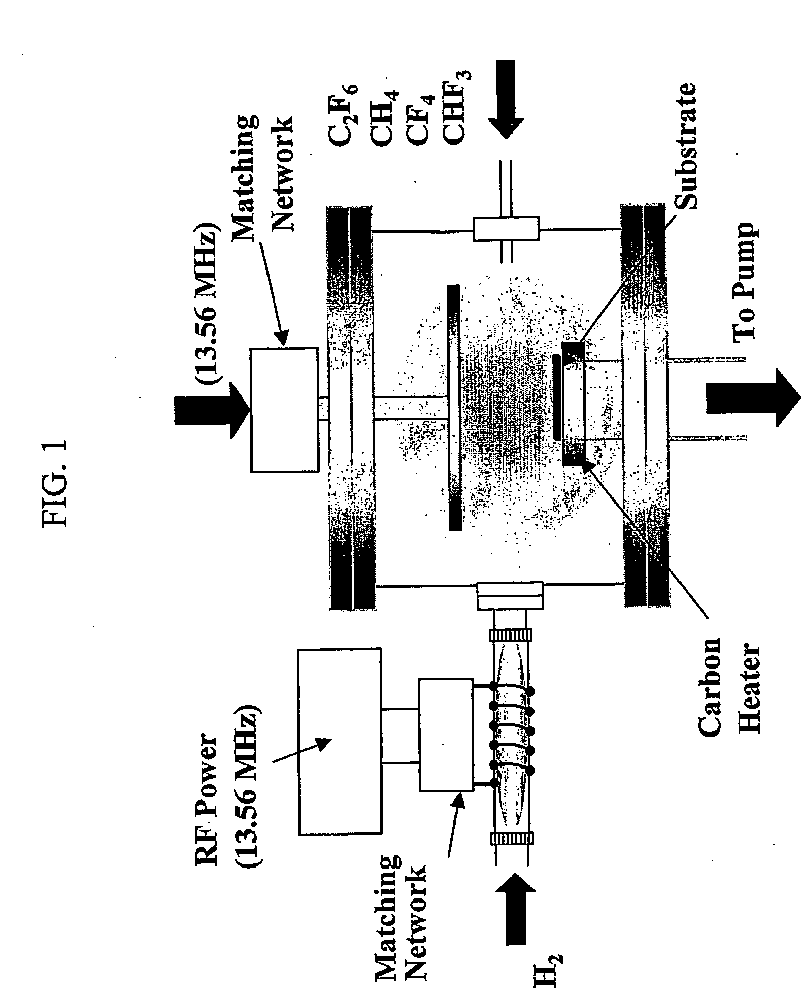
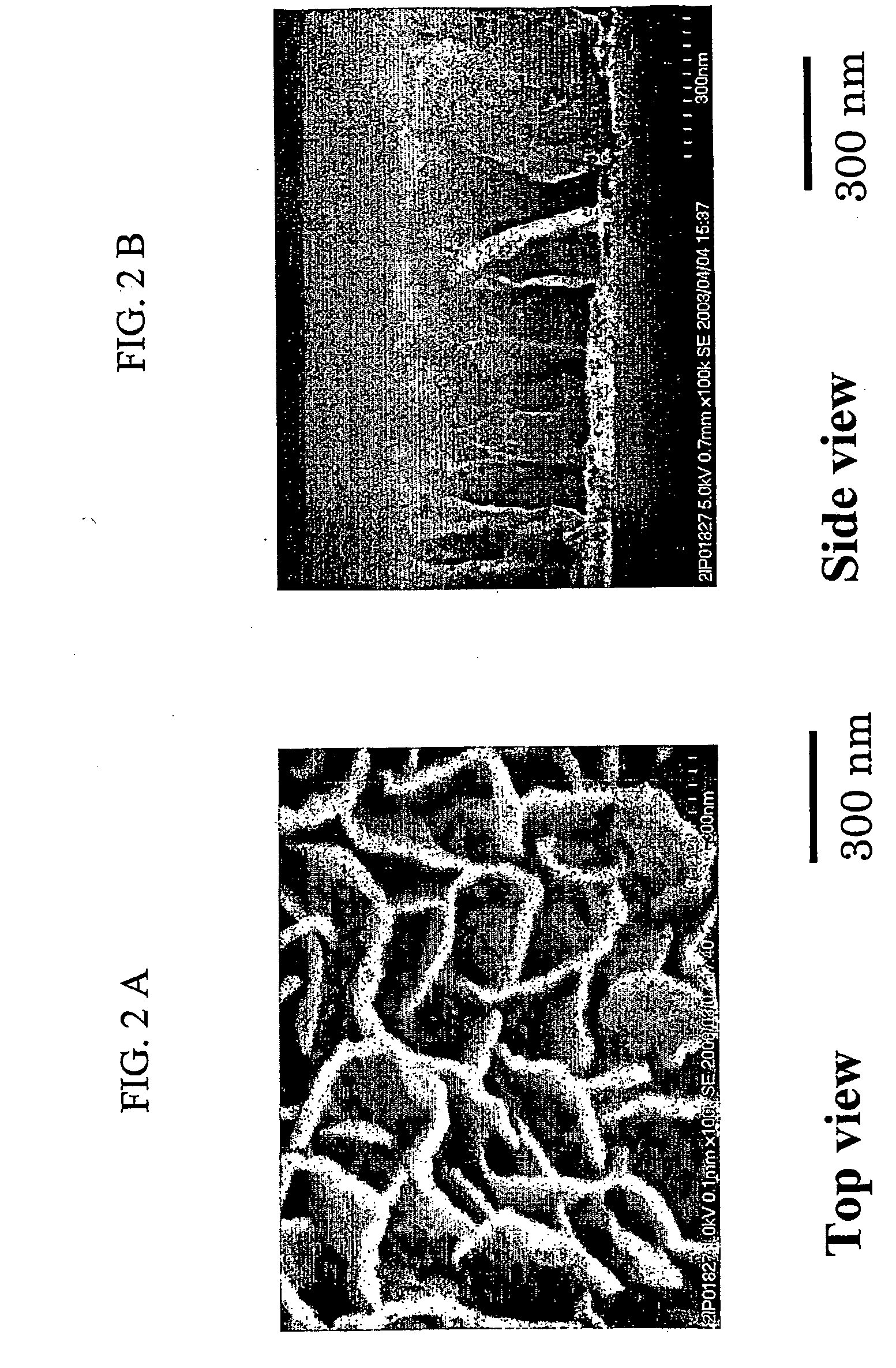
[0049]An example of a method of manufacturing a fuel cell separator with a rib portion formed with CNWs is described below, together with relevant manufacturing conditions. As a current collector plate, a stainless-steel plate measuring 30 mm×30 mm with a thickness of 0.11 mm was used. The stainless-steel plate was disposed in a chamber with a structure based on the above-described method of forming CNWs. C2F6 was then caused to flow into the chamber, and a channel with a desired shape was formed by address control over a period of eight hours. The height of the ribs was 1.4 μm. Using this structure as a separator, an FC small cell with an area of 1 cm2 was prepared, and its cell performance was measured.

example 2

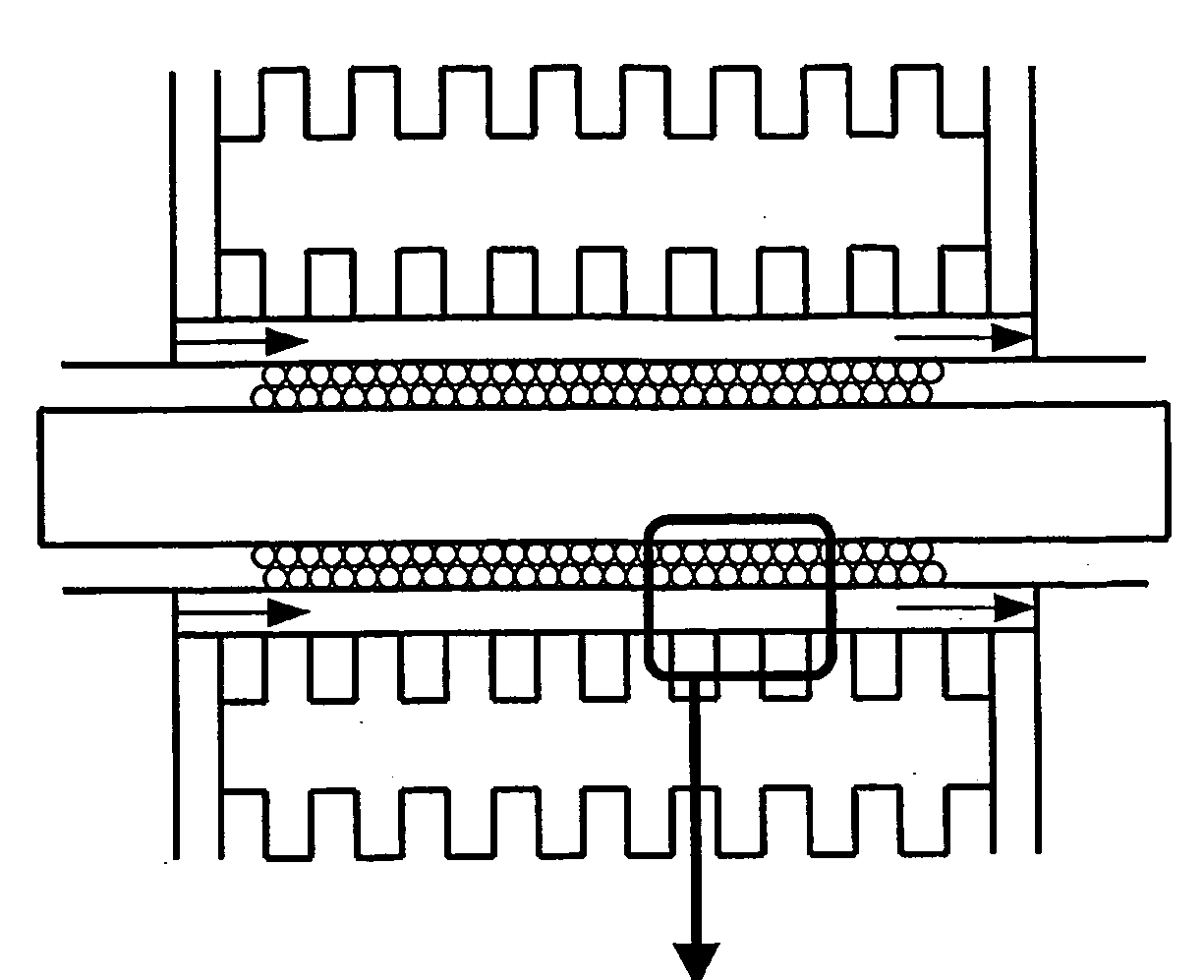
[0050]A current collector structure was prepared in which the CNW of Example 1 was further grown until it was integrated with the diffusion layer. The separator rib in a fuel cell has the role of feeding as much gas as possible to the reaction site and another role of enabling the current-collection to be performed effectively. Meanwhile, the diffusion layer in a fuel cell has the role of applying uniform pressure on the reaction electrodes so as to reduce contact resistance, as well as causing gases to flow below the gas channel ribs.

[0051]However, in the prior art, the diffusion layer and the separator are separate components, resulting in the problem of contact resistance and high cost. Other problems are also expected, such as one in which the behavior of the water produced by the fuel cell reaction at the contact portion becomes irregular.

[0052]To overcome these problems, CNWs were grown on a flat electrode plate (which may be either carbon or metal) until it was integrated wit...

example 3

[0056]The CNW patterns obtained in Examples 1 and 2 were subjected to hydrophilic / hydrophobic treatment so as to obtain a structure with an improved drainage property. The fuel cell separator ribs have the two roles, one to feed as much gas as possible to the reaction site, and the other to enable the current collection to be performed effectively. The diffusion layer in a fuel cell, on the other hand, has the role of causing gas to flow below the gas channel ribs, and another role of applying uniform pressure to the reaction electrodes so as to reduce contact resistance. The separator ribs and the diffusion layer are both typically provided with a water repellent treatment on the surface thereof so that the produced water can be drained effectively.

[0057]However, in the current state of the art, water-repellent treatment cannot be performed at appropriate portions of the diffusion layer and the separator. As a result, sufficient drainage property cannot be obtained.

[0058]Thus, the ...


PUM


Abstract

The degree of freedom in the shape of channels in a separator is increased, enabling an optimum gas channel to be designed, enabling a sufficient supply of gas below gas channel ribs, and improving cell performance through the reduction in diffusion polarization. Drainage property is also improved and flooding is prevented, thereby reducing diffusion polarization and improving cell performance. Cell performance is also improved through the reduction of contact resistance. A fuel cell separator comprises a separator substrate on which gas channel ribs are formed through vapor-phase growth of a carbon-based porous material with a nanosize structure. An electrode structure for a fuel cell, methods of manufacturing the separator and the fuel cell, and a solid polymer fuel cell comprising the electrode structure.

Description

TECHNICAL FIELD[0001]The present invention relates to a fuel cell separator With gas channel ribs made of a nanoporous material, an electrode structure for a fuel cell, methods of manufacturing the fuel cell separator and the fuel cell structure, and a polymer electrolyte fuel cell.BACKGROUND ART[0002]A solid polymer fuel cell is comprised of a stack of single cells and two current collectors disposed on the outside of the stack. Each of the single cells consists of a solid polymer electrolyte membrane, two electrodes disposed on both sides of the solid polymer electrolyte membrane, and separators with gas-feeding grooves for feeding a fuel gas, such as hydrogen, and an oxidant gas, such as oxygen, to each of the electrodes.[0003]The separators in the solid polymer fuel cell are required to have high levels of gas impermeability so as to allow the fuel gas and oxidant gas to be fed to the electrodes completely separately. In addition, the internal resistance of the battery is requir...

Claims


Application Information

Patent Timeline
IPC IPC(8): H01M8/02H01M4/96B05D5/12
CPCH01M8/0228H01M8/0234H01M8/0245H01M8/0252Y10S977/948H01M8/0263H01M8/1002Y02E60/521H01M8/0258H01M8/1007H01M8/02B82Y30/00Y02P70/50
Inventor HORI, MASARUHIRAMATSUKANO, HIROYUKIKATAYAMA, YUKIHISASUGIYAMA, TORUYOSHIDA, SATOSHI
Owner HORI MASARU
Why Eureka
Try Eureka