
Camera system with a full view monitoring function

a full-view, monitoring function technology, applied in the field of camera systems, can solve the problems of indistinct edges of panorama images, inability to clearly provide detailed characteristics, and inability to change the orientation of fisheye cameras, so as to effectively identify any subtle differences

Active Publication Date: 2015-12-08
GEOVISION
View PDF8 Cites 13 Cited by
  • Summary
  • Abstract
  • Description
  • Claims
  • Application Information

AI Technical Summary

Benefits of technology

The invention is about a camera system that includes two cameras: one fixed and wide-angle, and another that is mobile and can capture images from different angles. The wide-angle camera can be distorted, so the mobile camera can be used to capture a narrower-angle image for added clarity. This allows for automatic compensation and full-view observation, as well as local magnification, to identify subtle changes in the environment.

Problems solved by technology

Capturing orientation of the fisheye camera is unchangeable, and the fisheye camera captures a panorama image to view a large area within an environment.
However, the edge of the panorama image may be indistinct because of optical distortion phenomenon, and cannot clearly provide detailed characteristic for image identification.
The PTZ camera cannot capture the panorama image, so that application of the PTZ camera is unable to monitor the wide public place.

Method used


Image

  • Camera system with a full view monitoring function
  • Camera system with a full view monitoring function
  • Camera system with a full view monitoring function

Examples


Embodiment Construction

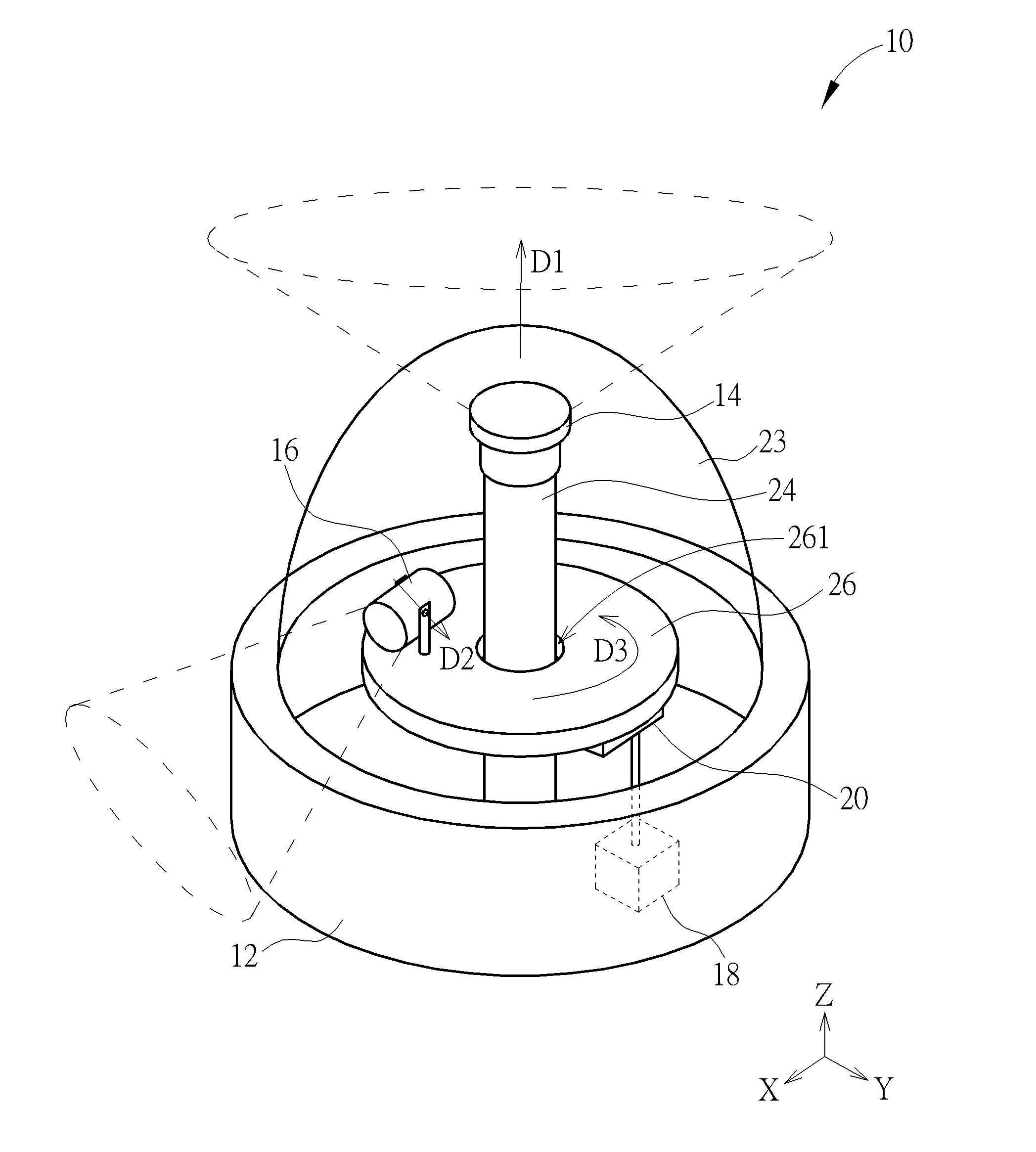
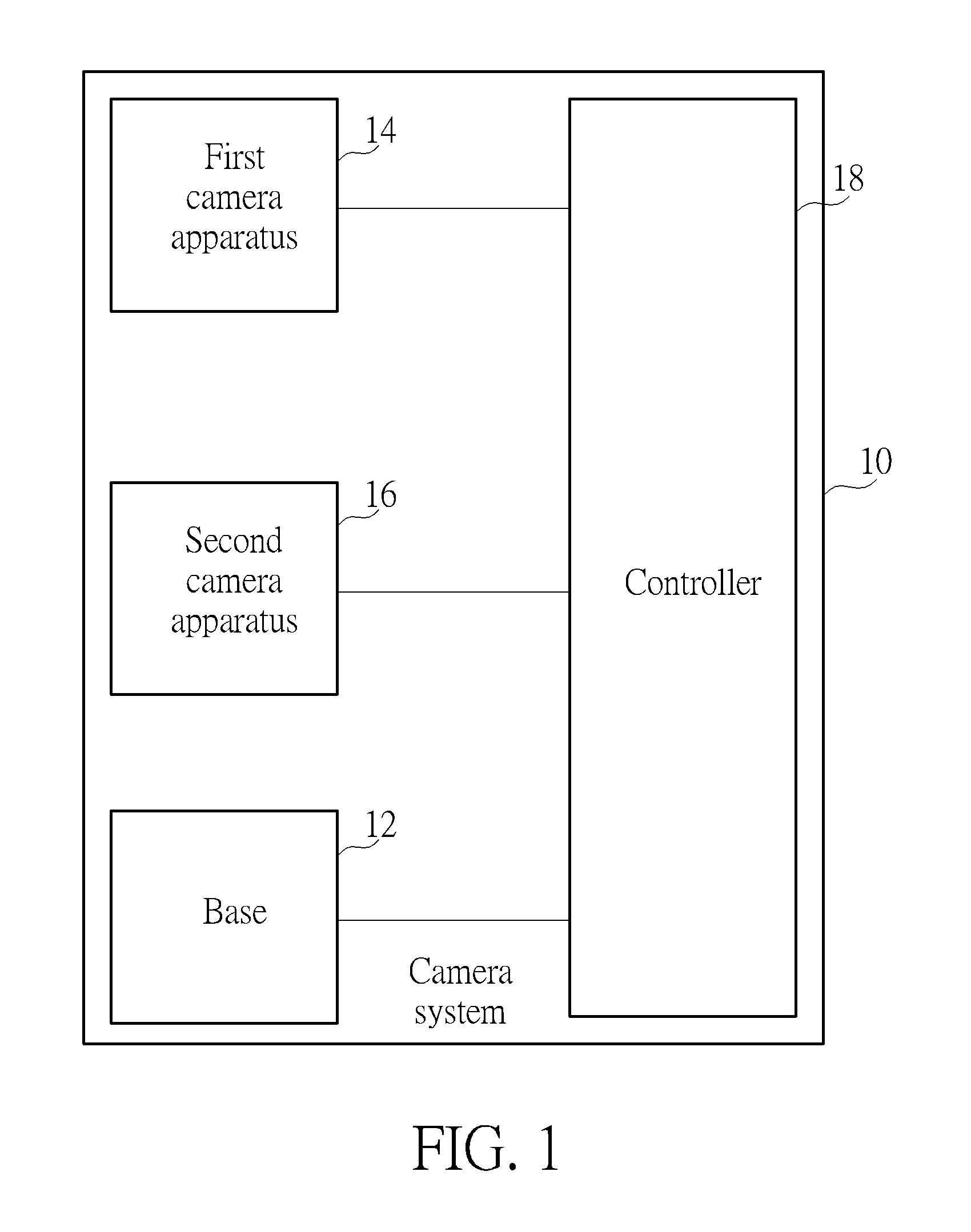
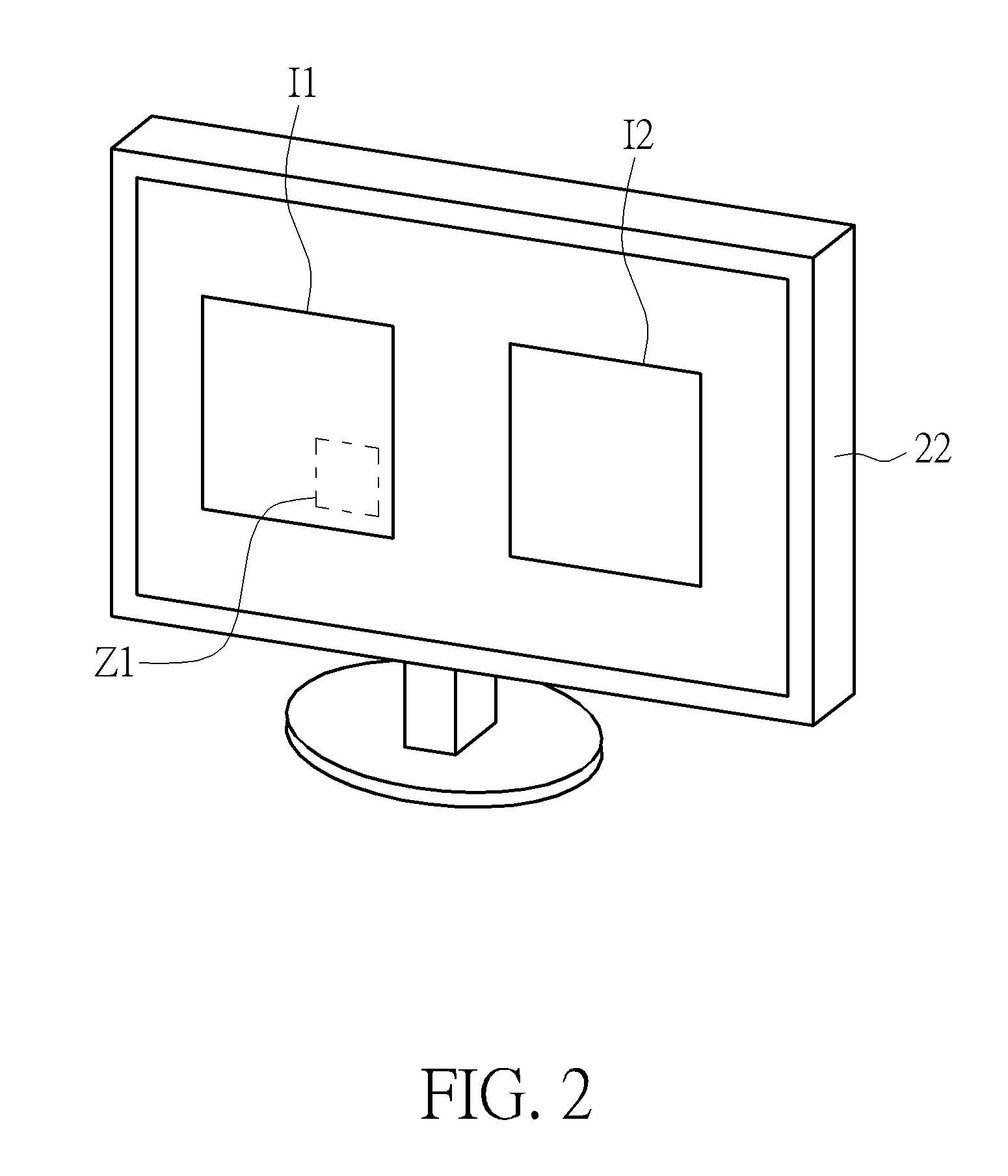
[0028]Please refer to FIG. 1 to FIG. 3. FIG. 1 is a functional block diagram of a camera system 10 according to an embodiment of the present invention. FIG. 2 is a diagram of a display panel 22 applied to the camera system 10 according to the embodiment of the present invention. FIG. 3 is a structural diagram of the camera system 10 according to the embodiment of the present invention. The camera system 10 includes a base 12, a first camera apparatus 14, at least one second camera apparatus 16, a controller 18, a rotating mechanism 20 and the display panel 22. The first camera apparatus 14 is fixed on the base 12 and invariably faces toward a first direction D1. The first camera apparatus 14 can be a fisheye camera and is adapted to capture a panorama image I1. The second camera apparatus 16 is movably disposed on the base 12 by the rotating mechanism 20 and adjustably faces toward a detecting direction which is different from the first direction D1. For example, the first direction...


PUM


Abstract

A camera system with a full view monitoring function includes a base, a first camera apparatus, at least one second camera apparatus and a controller. The first camera apparatus is fixed on the base and invariably faces toward a first direction. The first camera apparatus is adapted to capture a panorama image. The second camera apparatus is movably disposed on the base and adjustably faces toward a detecting direction different from the first direction. The second camera apparatus is adapted to encircle around the first camera apparatus. The controller is electrically connected to the first camera apparatus and the second camera apparatus. The controller is adapted to analyze the panorama image to filter out a triggering zone, to encircle the second camera apparatus toward a detecting direction corresponding to the triggering zone, and to drive the second camera apparatus to capture a detecting image overlapping the triggering zone.

Description

BACKGROUND OF THE INVENTION[0001]1. Field of the Invention[0002]The present invention relates to a camera system, and more particularly, to a camera system with a full view monitoring function.[0003]2. Description of the Prior Art[0004]A monitoring system is extensively applied to the public place, such as the train station, the supermarket, the street and so on. A fisheye camera or a PTZ camera is applied to the conventional monitoring system. Capturing orientation of the fisheye camera is unchangeable, and the fisheye camera captures a panorama image to view a large area within an environment. However, the edge of the panorama image may be indistinct because of optical distortion phenomenon, and cannot clearly provide detailed characteristic for image identification. The PTZ camera represents the camera lens can be panned, tilted and zoomed in / out to capture the small-size image. The PTZ camera cannot capture the panorama image, so that application of the PTZ camera is unable to m...

Claims


Application Information

Patent Timeline
Patent Type & Authority Patents(United States)
IPC IPC(8): H04N5/225H04N5/232H04N5/247G08B13/196H04N7/18H04N23/90
CPCG08B13/19641H04N7/181G08B13/19645H04N5/23238H04N5/23296H04N5/2253H04N5/247G08B13/19628G08B13/1963G08B13/19643H04N23/50H04N23/698H04N23/90
Inventor WU, CHIH-MINGHSU, CHUN-KAILEE, CHUN-TAO
Owner GEOVISION
Learn More