Lighting assembly for reel slot machine

a technology of light assembly and reel slot machine, which is applied in the direction of meter-controlled dispensers, instruments, coin-freed devices, etc., can solve the problems of corresponding reel tilt and/or drive motor overload, undesirable gaps in the appearance of reels, and partial or complete failure of cross links, etc., to achieve reliable placement and maintenance of gaming icons

Active Publication Date: 2015-12-15
IGT
View PDF33 Cites 1 Cited by
  • Summary
  • Abstract
  • Description
  • Claims
  • Application Information

AI Technical Summary

Benefits of technology

[0011]To address reel assembly life cycle degradation and assembly issues seen in the prior art, in one embodiment, by way of example only, a reel assembly is provided for use in a mechanical gaming device including a substantially continuous, and in one example, integral support substrate extending between an inner drive ring and an outer ring of the reel assembly. The substantially continuous support substrate provides for robust coupling of the inner drive ring to the outer ring that is more suitable for use over the many start and stop cycles of a gaming machine. The substantially continuous support substrate also provides for a more reliable placement and maintenance of gaming icons on the reel assembly. In one example, the support substrate is substantially transparent such that the support substrate casts little or no shadows when the reel strips are backlit for additional aesthetic appeal. In one example, the continuous support substrate also allows for registration via mechanical indexing without requiring the reel assembly to include additional dedicated registration structure.
[0012]To address the complicated light structures seen in the prior art and a desire to both illuminate reel assemblies and provide side lighting between reel assemblies, in one embodiment, by way of example only, a light assembly is provided for use with a reel assembly that makes use of a printed circuit board as light support, which reduces the need for brackets and / or the number of electrical connections that must be made during installation of the light assemblies. In one example, a single flexible printed circuit board supports lights for a reel assembly and an adjacent sidelight. In one example, a single light is directed and dispersed to illuminated a designated area of the reel assembly increasing options for differentiating illumination of a reel assembly for different occurrences during game play and / or during rebranding or overhaul of a gaming machine for aesthetically differentiated games.

Problems solved by technology

For example, the tangential forces from repeated spinning and stopping cycles for a typical reel assembly 44 often results in overstressing of the cross links 56, which may lead to partial or complete failure of the cross links 56 and corresponding reel tilt and / or drive motor overload.
In addition, prolonged periods of use of the reel assemblies 44 gradually causes wear and additional play is introduced to the reel assemblies 44 further resulting in undesirable gaps in the appearance of the reel assemblies 44 and distracting wobble when the reel assemblies are rotating.
Furthermore, adhered ends of the reel strip 46 often become loose and / or uncouple from one another potentially leading to release of the reel strip 46 or a portion thereof from a remainder of the reel assembly 44.
However, the cross links 56 may create undesired shadowing across the reel strip 46 when exposed to such lighting.
Making the cross links 56 thinner may minimize the shadow effect, but also weakens the overall structural integrity of the reel assembly 44.
Additionally, the e-clip 78 is relatively small in size contributing to the likelihood that it will be inadvertently lost during routine maintenance of the reel assembly 44.
The large number of wires and electrical connections that need to be made between the separate PCB boards increases the cost and complexity of installation and servicing.

Method used


Image

  • Lighting assembly for reel slot machine
  • Lighting assembly for reel slot machine
  • Lighting assembly for reel slot machine

Examples


Embodiment Construction

[0050]The following detailed description of the invention merely provides exemplary embodiments and is not intended to limit the invention or the application and uses of the invention. Furthermore, there is no intention to be bound by any theory presented in the preceding background of the invention or the following detailed description of the invention.

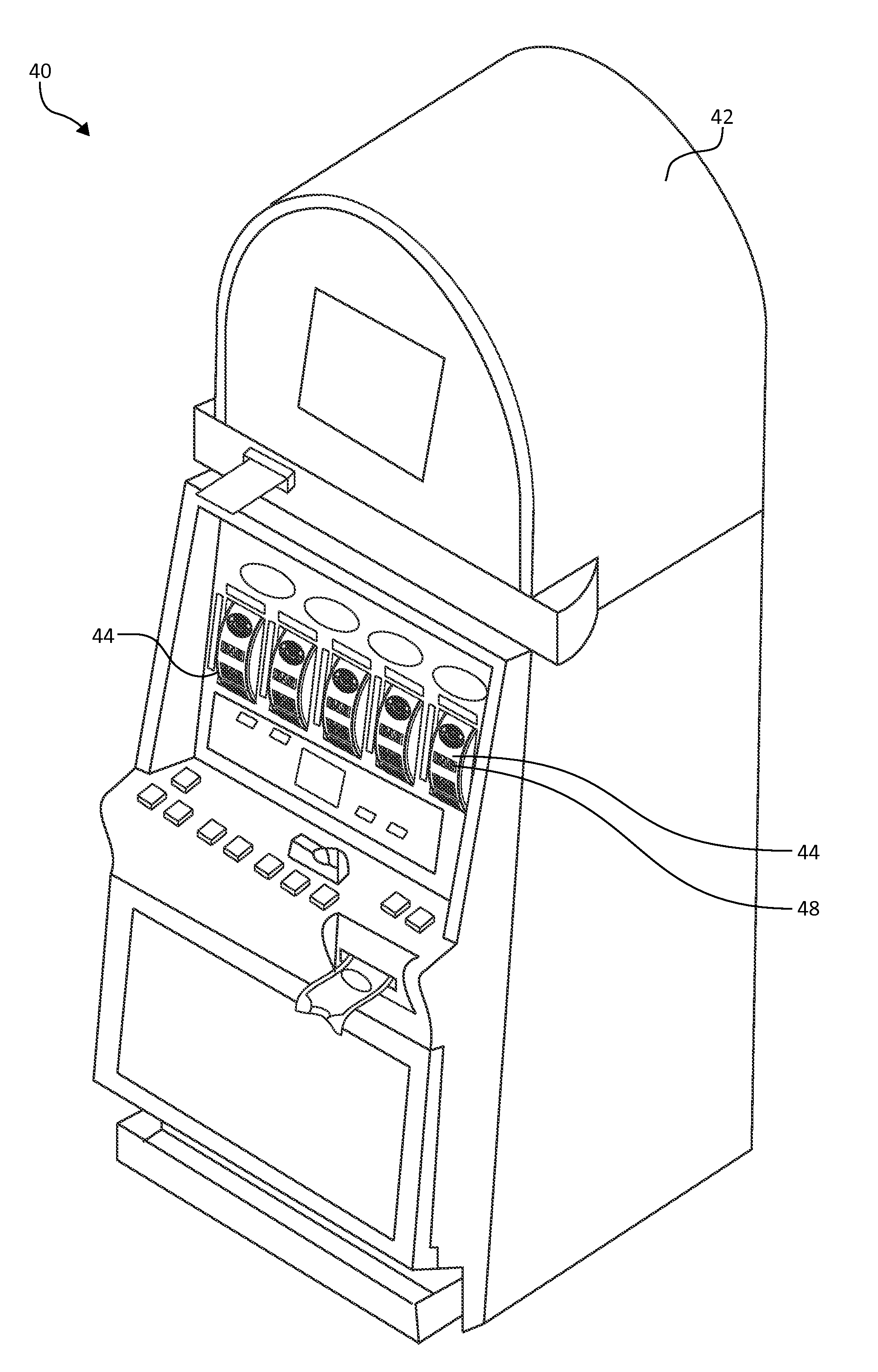
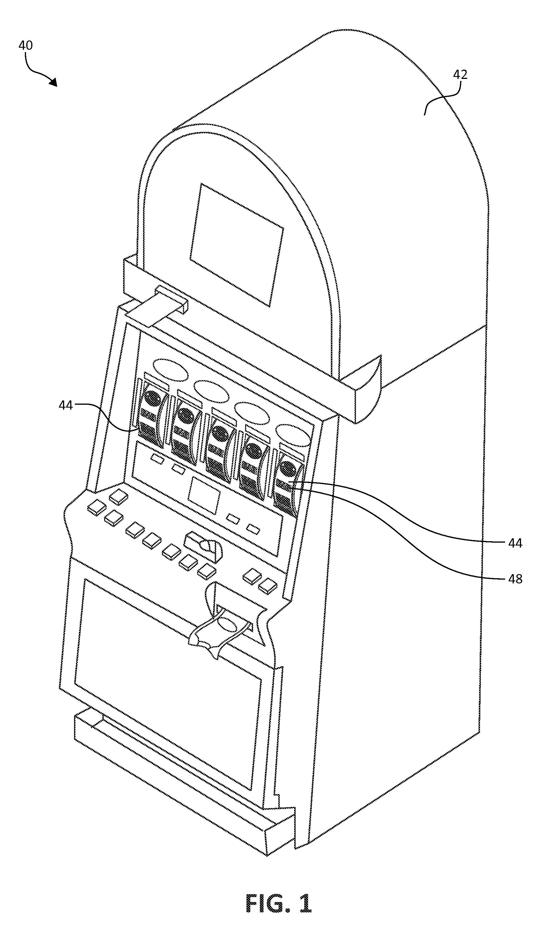
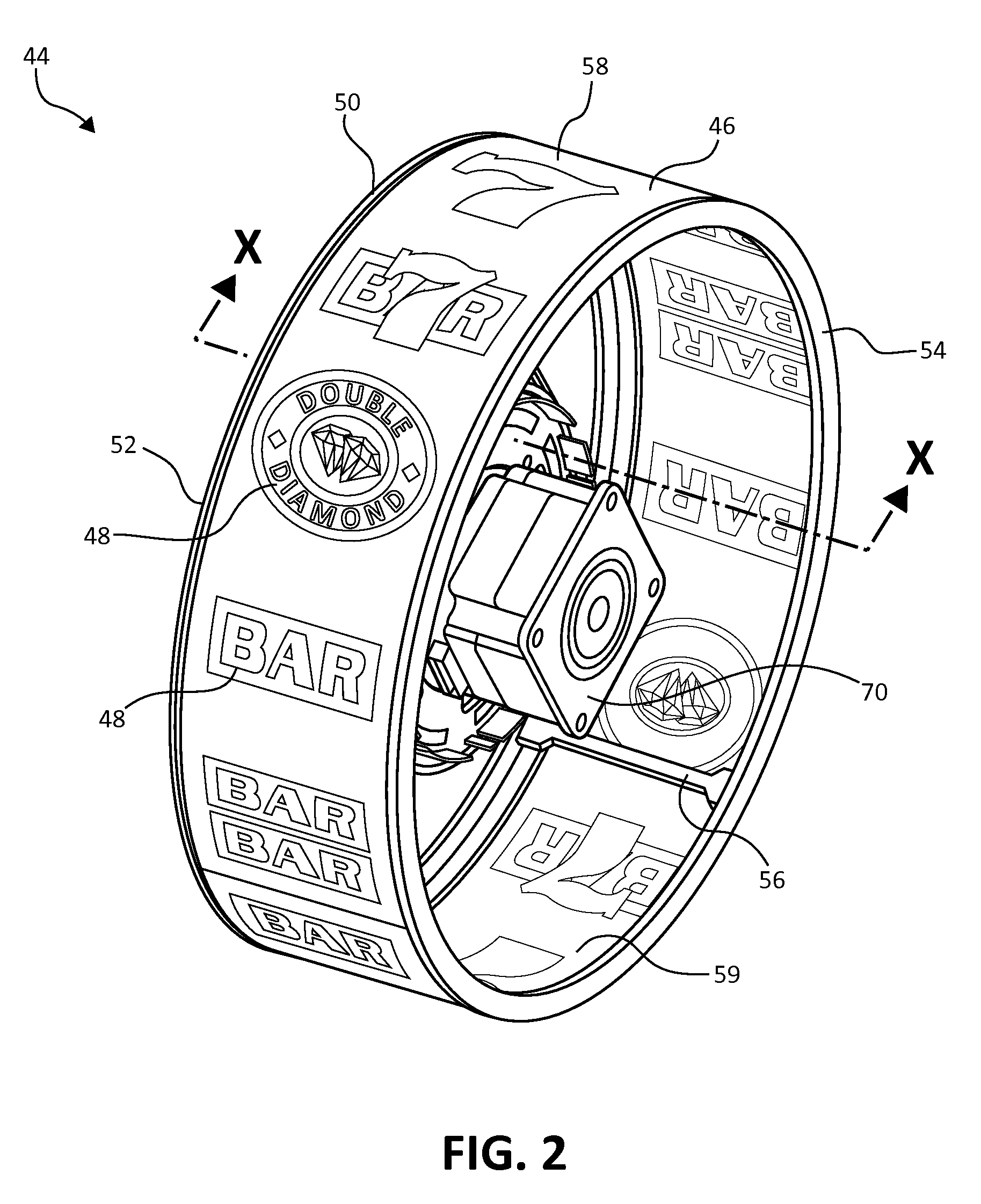
[0051]Embodiments of the present invention are described below provide improved reel assemblies and associated lighting assemblies. The reel assemblies generally provide continuous support between an inner drive ring and an outer ring of a reel assembly providing for a more stable coupling between the inner drive ring and the outer ring, but also providing a more continuous support for an associated reel strip, providing little to no shadowing upon backlighting thereof, and being suitable for longer periods of use with lessened degradation of the reel assembly or its coupling to a gaming machine. Light assemblies according to the pre...


PUM

PropertyMeasurementUnit
transparentaaaaaaaaaa
angleaaaaaaaaaa
electricallyaaaaaaaaaa

Abstract

A lighting assembly for a reel slot machine includes an interface board and a flexible printed circuit board (PCB). The interface board is substantially planar, electrically couplable to the reel slot machine, and includes a first electrical connection plug and a second electrical connection plug spaced from the first electrical connection plug. The flexible PCB defines a first end and a second end, the first end and second ends of the flexible PCB are electrically coupled to the first electrical connection plug and the second electrical connection plug, respectively. The flexible PCB bows away from each of the first and second ends to define a bowed primary face facing away from the interface board. The flexible PCB further comprises a plurality of light sources coupled to the bowed primary face. During use, the plurality of light sources selectively illuminate to provide lighting to a reel of the reel slot machine.

Description

CROSS-REFERENCE TO RELATED APPLICATION[0001]This application is a continuation application of, and claims priority under 35 U.S.C. §120 to U.S. patent application Ser. No. 14 / 258,441, filed Apr. 22, 2014, which is a non-provisional application of and claims priority under 35 U.S.C. §119 to U.S. Provisional Patent Application No. 61 / 890,460, filed Oct. 14, 2013, which are both incorporated herein by reference.FIELD OF THE INVENTION[0002]The present disclosure relates generally to wager-based gaming machines and, more specifically, to new and improved wager-based gaming machines having mechanical, spinning reels.BACKGROUND OF THE INVENTION[0003]Wager-based gaming is a multi-billion dollar industry with sustained popularity. Gaming entities, such as casinos appeal to many different audiences and provide one or more of a variety of available different gaming devices. Mechanical reel gaming machines are a staple of the gaming industry. FIG. 1 illustrates one example of a mechanical reel ...

Claims


Application Information

Patent Timeline
Patent Type & Authority Patents(United States)
IPC IPC(8): G06F17/00G07F17/32
CPCG07F17/3213G07F17/3202G07F17/3216G07F17/32G07F17/3293G07F17/34Y10T29/49826
Inventor CRIVELLI, FRANCO E.MIKHAIL, ESSAMHERNANDEZ, JUAN C.GARAMENDI, MICHAEL T.FRABBIELE, ANTHONY J.JONES, SCOTT H.BEADELL, JOHN L.GOWIN, SCOTT T.
Owner IGT
Why Eureka
Try Eureka