Heat-generating shoe

a technology for heat-generating shoes and shoes, applied in the field of heat-generating shoes, can solve the problems of difficulty in replacing the battery of the heat-generating shoe, easy current leakage of the battery, and damp or damage to the affected area,

Active Publication Date: 2015-12-22
TSENG SHEN KO
View PDF11 Cites 27 Cited by
  • Summary
  • Abstract
  • Description
  • Claims
  • Application Information

AI Technical Summary

Benefits of technology

[0008]Therefore, in order to improve the problem described previously, a scope of the present invention is to provide a heat-generating shoe which can convert the kinetic energy of walking into electrical energy. Furthermore, this heat-generating shoe not only solves the problem of battery but also supplies thermal energy for preventing users from frostbite in cryogenic environment.
[0019]According to the embodiments described above, the heat-generating shoe of the present invention provides a variety of types of power generation devices, so a suitable power generation device can be adopted depending on the power demand, thickness of heat-generating shoe, and / or costs. In addition, the present invention produces electrical energy by applying a force to the shoe body without replacing the battery, so as to generate power automatically during the user walking. More particularly, the heating device of power generation device can increase the temperature inside the shoe body for preventing users from frostbite in cryogenic environment, and additionally, the electrical energy produced thereof can be transmitted to external electrical devices. Moreover, the display device of the present invention uses different colors to show the dump energy of the electricity storing device, contributing a great convenience for users.

Problems solved by technology

However, the thin batteries contain mercury (Hg), a toxic heavy metal that can result in environmental contamination.
Moreover, if the accompanied heat-generating devices are without waterproof, the batteries thereof would be easy to leak current, be affected with damp or damage.
For a heat-generating shoe, the battery thereof is configured within the shoe body, leading to the difficulty to replace the battery in the heat-generating shoe.

Method used


Image

  • Heat-generating shoe
  • Heat-generating shoe
  • Heat-generating shoe

Examples


Embodiment Construction

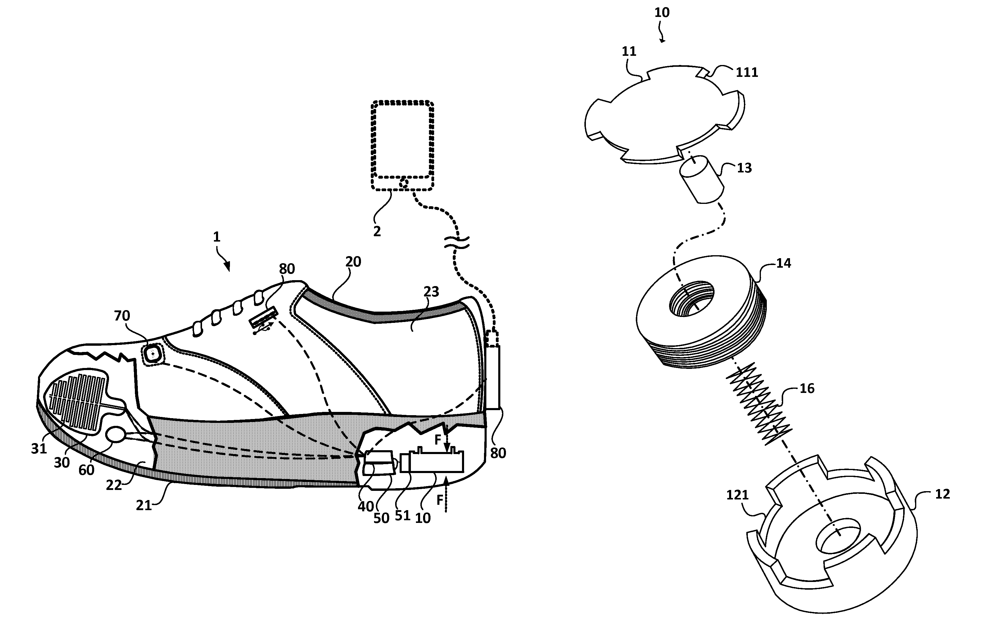
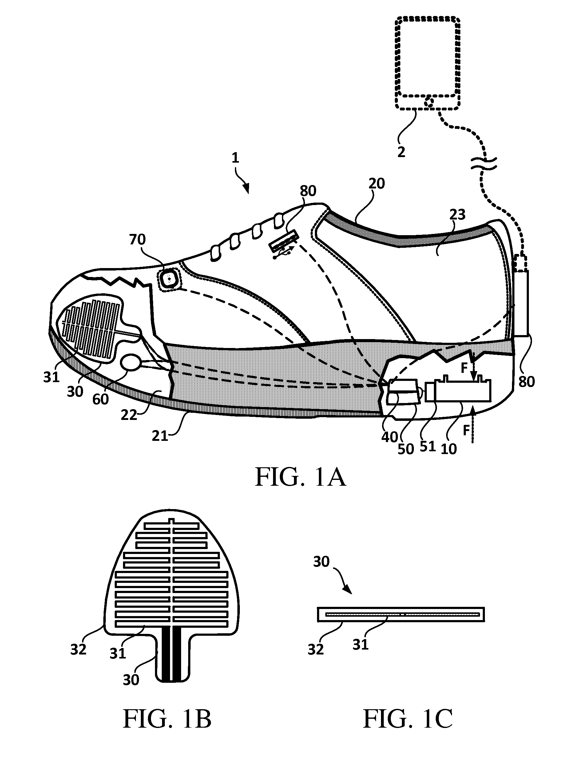
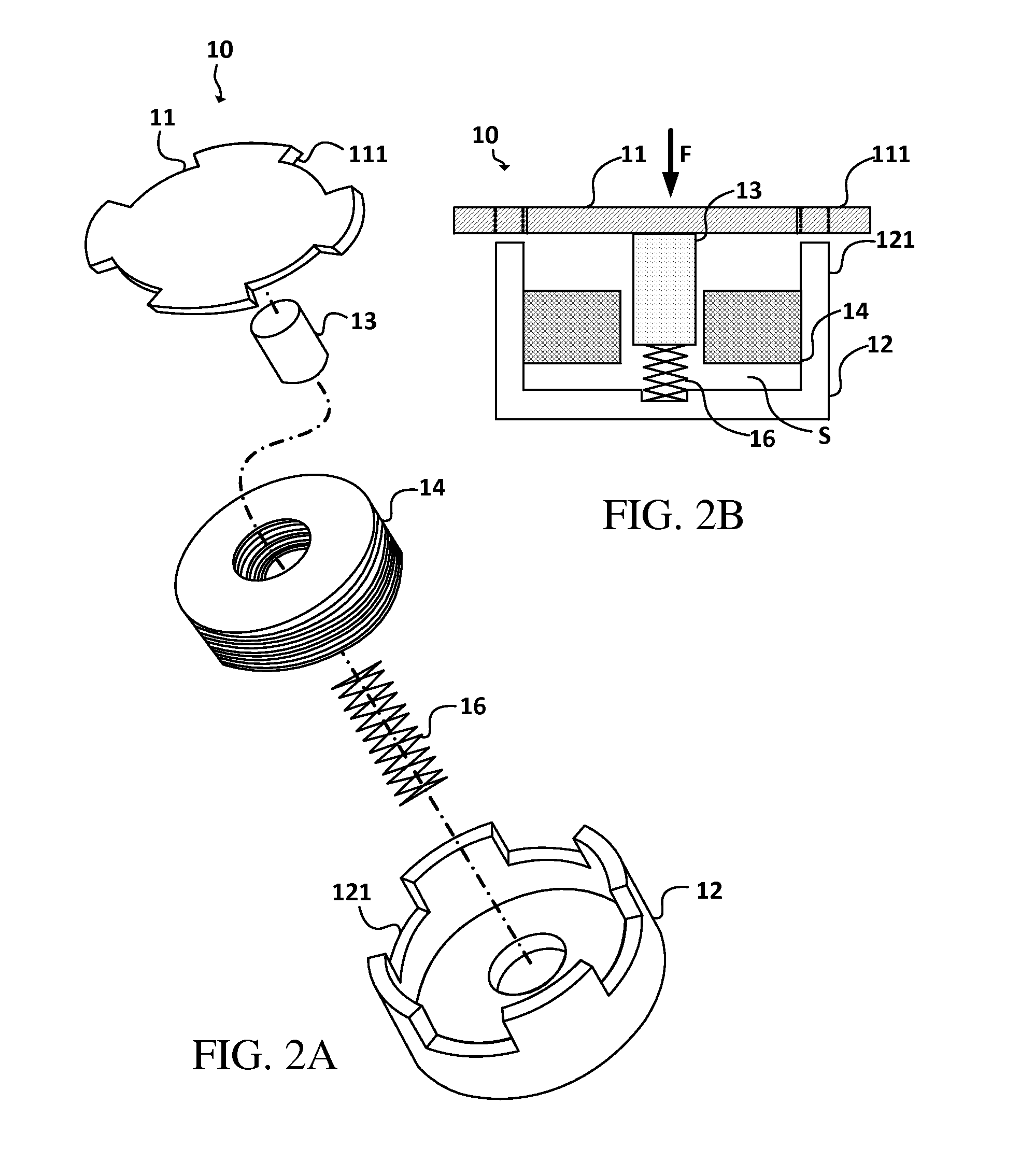
[0042]The present invention discloses a heat-generating shoe which utilizes electromagnetic induction or piezoelectricity unit to produce electrical energy for thermal insulation and heat generation. Please refer to FIG. 1A to 1C. FIG. 1A is a schematic diagram illustrating a heat-generating shoe according to an embodiment of the invention. FIG. 1B is a top view illustrating a heat-generating device according to an embodiment of the invention. FIG. 1C is a sectional view illustrating a heat-generating device according to an embodiment of the invention. As shown in FIG. 1A, the heat-generating shoe comprises a power generation device 10, a shoe body 20, a heating device 30, a control device 40, an electricity storing device 50, a rectifying device 51, a temperature sensing device 60, a display device 70, and an interface device 80.

[0043]In one of the embodiment, the shoe body 20 comprises a bottom 21, an inner surface 22 and an outer surface 23. The shoe body 20 bears a force F when ...


PUM


Abstract

A heat-generating shoe comprises a power generation device. When applying a force to the heat-generating shoe, the power generation device with applied force produces electrical energy by electromagnetic induction or piezoelectric effect without external power supply or replacing the battery, so as to generate power automatically during the user walking. More particularly, the present invention can increase the temperature inside the shoe body for preventing users from frostbite in cryogenic environment. Additionally, the present invention provides a variety of types of power generation devices, so a suitable power generation device can be adopted depending on the power demand, thickness of heat-generating shoe, and / or costs.

Description

BACKGROUND OF THE INVENTION[0001]1. Field of the Invention[0002]The present invention relates to a heat-generating shoe, and more particularly to a heat-generating shoe utilizing electromagnetic induction or piezoelectricity unit to produce electrical energy for thermal insulation and heat generation.[0003]2. Description of the Prior Art[0004]In order to raise public environmental awareness, more and more green products are developed and manufactured. Wherein, there are some products utilizing simple mechanism to produce electrical energy, for example, a hand-pressing flashlight and a power-generation bicycle.[0005]Additionally, people need to prevent frostbite in cryogenic environment. Frostbite occurs when skin and other tissues are exposed to very cold temperatures, especially in toes owing to that the vascularity (density of blood vessels) of toes is lower than other body parts. Therefore, a heat-generating shoe is one of the solutions to improve the problem mentioned above.[000...

Claims


Application Information

Patent Timeline
Patent Type & Authority Patents(United States)
IPC IPC(8): A43B7/02A43B1/00A43B3/00A43B7/04A43B3/35
CPCA43B7/02A43B7/04A43B3/0015A43B1/0054A43B3/38A43B3/35
Inventor TSENG, SHEN-KO
Owner TSENG SHEN KO
Why Eureka
Try Eureka