
Liquid ejection head

a technology of liquid ejection and sealing member, which is applied in the direction of printing and inking apparatus, etc., can solve the problems of reducing the ejection accuracy (landing accuracy) of liquid, hindering good printing, and relative so as to achieve the effect of reducing the relative position reducing the misalignment of recording element substrates

Active Publication Date: 2015-12-22
CANON KK
View PDF4 Cites 0 Cited by
  • Summary
  • Abstract
  • Description
  • Claims
  • Application Information

AI Technical Summary

Benefits of technology

The present invention is a liquid ejection head that can be used for various shapes of recording element substrates. It reduces misalignment between the substrates and makes it easy to adjust the accuracy of their relative positions. The joint that connects the substrates is protected by the sealing member, which also reduces stress and rotational force. This protects the connection and ensures equal or minimal difference in the stresses applied to the substrates.

Problems solved by technology

Of liquid ejection heads, recording element substrates having a parallelogram planar shape and the configuration in which at least first side portion of inclined recording element substrates, as disclosed in U.S. Pat. No. 6,609,786, is covered with a sealing member can cause relative misalignment due to cure shrinkage of the sealing member.
The misalignment of the recording element substrates from proper positions can cause misalignment of the landing positions of ejected liquid, thus hindering good printing.
This problem occurs not only in a line head having a plurality of recording element substrates, as disclosed in PCT Japanese Translation Patent Publication No. 2010-521343 and U.S. Pat. No. 6,609,786, but also in a compact liquid ejection head having only one recording element substrate that ejects liquid while moving, that is, a so-called serial head.
In particular, a line head in which a plurality of recording element substrates are disposed, as disclosed in PCT Japanese Translation Patent Publication No. 2010-521343, causes the above problem in each of the recording element substrates and also a decrease in the ejection accuracy (landing accuracy) of liquid due to the decrease in the accuracy of the relative position of the recording element substrates.
Using such liquid ejection heads in ink-jet printers would cause streaks and non-uniformity in an image formed by ejecting liquid, thus degrading the image quality.
Furthermore, in the configuration disclosed in PCT Japanese Translation Patent Publication No. 2010-521343, a plurality of recording element substrates are mounted on one long support structure, so that even one problem in the plurality of recording element substrate would make the entire head unavailable.
Thus, its manufacturing process and adjusting work are complicated.

Method used


Image

  • Liquid ejection head
  • Liquid ejection head
  • Liquid ejection head

Examples


first embodiment

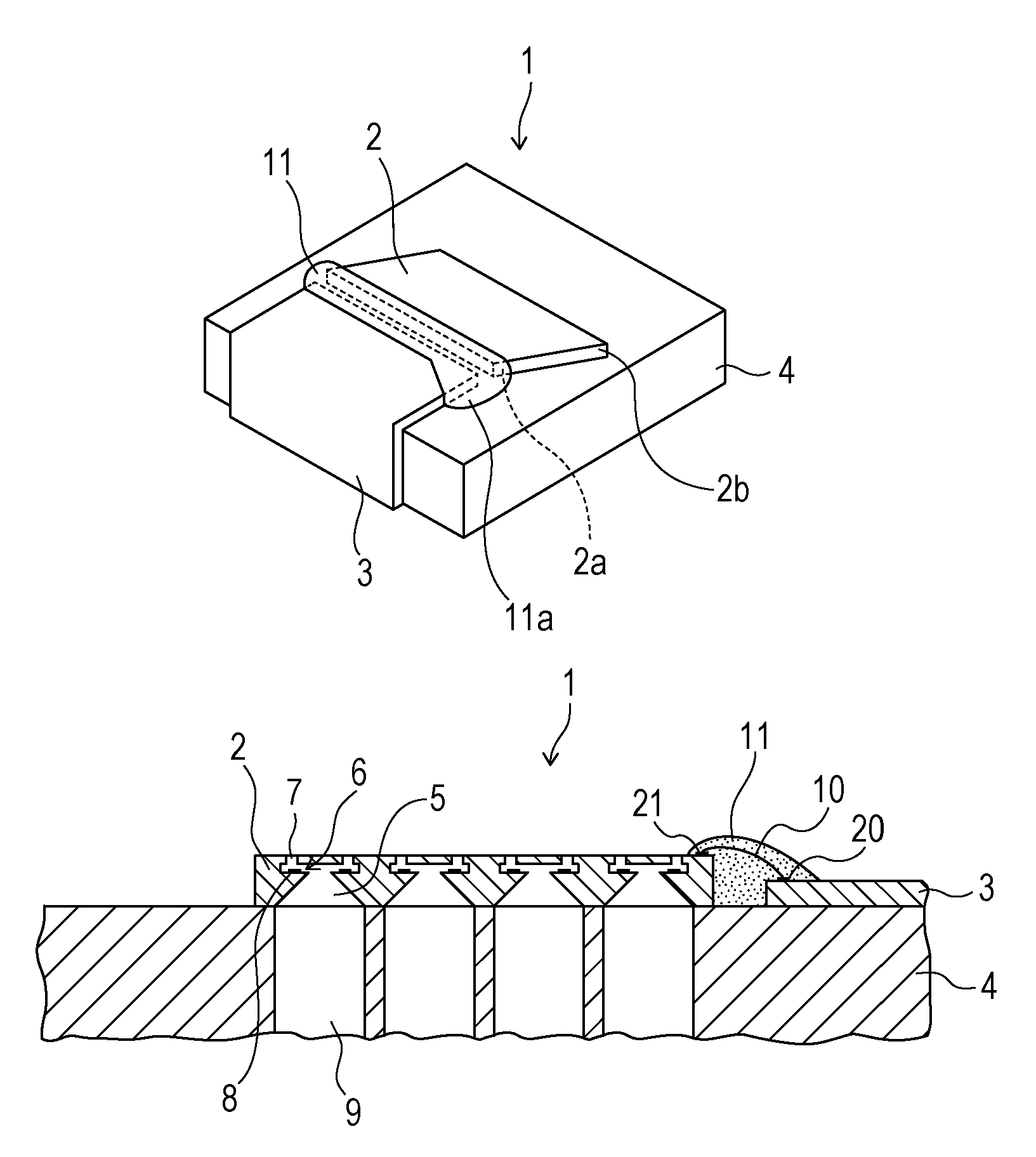
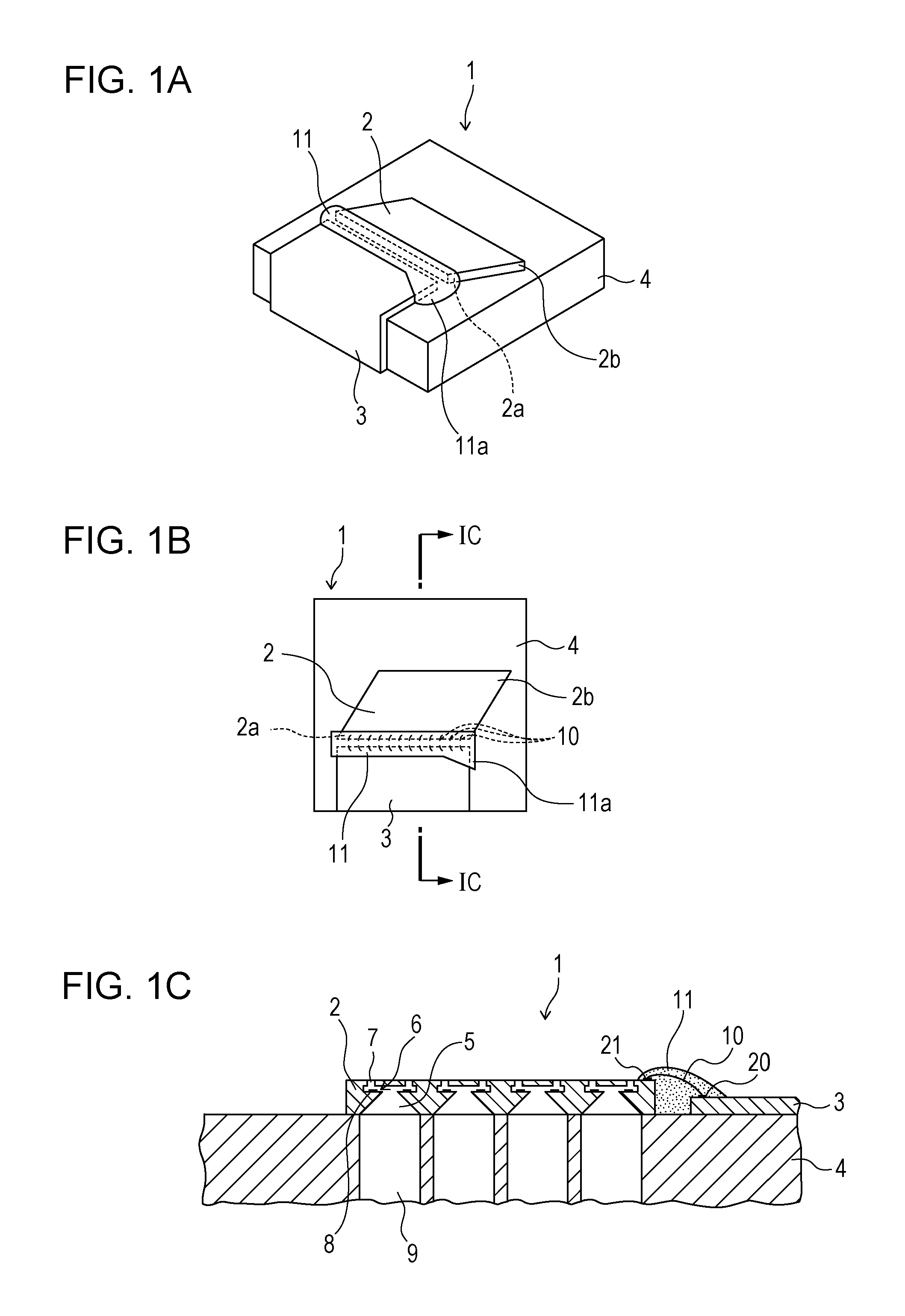
[0035]Referring to FIGS. 1A to 1C, a liquid ejection head 1 according to a first embodiment of the present invention will be described. FIG. 1A is a perspective view of the liquid ejection head 1 of this embodiment, FIG. 1B is a plan view thereof, and FIG. 1C is a cross-sectional view taken along line IC-IC of FIG. 1B. The liquid ejection head 1 is a serial-type compact head including a recording element substrate 2, an electrical wiring substrate 3, and a support member 4. The recording element substrate 2 has a substantially parallelogram planar shape and includes supply paths 5 through which liquid, such as ink, is supplied, energy generating chambers 6 communicating with the supply paths 5, and ejection ports 7 communicating with the energy generating chambers 6 and open to the outside. The plurality of ejection ports 7 are disposed in a line. The energy generating chambers 6 each have a recording element 8 therein for generating energy for ejecting liquid. That is, the energy g...

second embodiment

[0054]Next, a second embodiment of the present invention shown in FIG. 6A will be described. This embodiment includes a deformation preventing member 12 made of resin for covering the second side portion 2b of the recording element substrate 2, in addition to the sealing member 11 for protecting the connecting members 10 provided between the first side portion 2a of the recording element substrate 2 and the electrical wiring substrate 3. The deformation preventing member 12 may be made of a resin material or the same resin as that of the sealing member 11. The technical significance of the deformation preventing member 12 will be described hereinbelow.

[0055]Another cause of misalignment of the recording element substrate 2 in the known liquid ejection head 1 may be concentration of stress due to the cure shrinkage of the sealing member 11. PCT Japanese Translation Patent Publication No. 2010-521343 discloses the configuration in which the electrical wiring substrate 3 is disposed on...

third embodiment

[0062]A third embodiment of the present invention shown in FIG. 7A will be described.

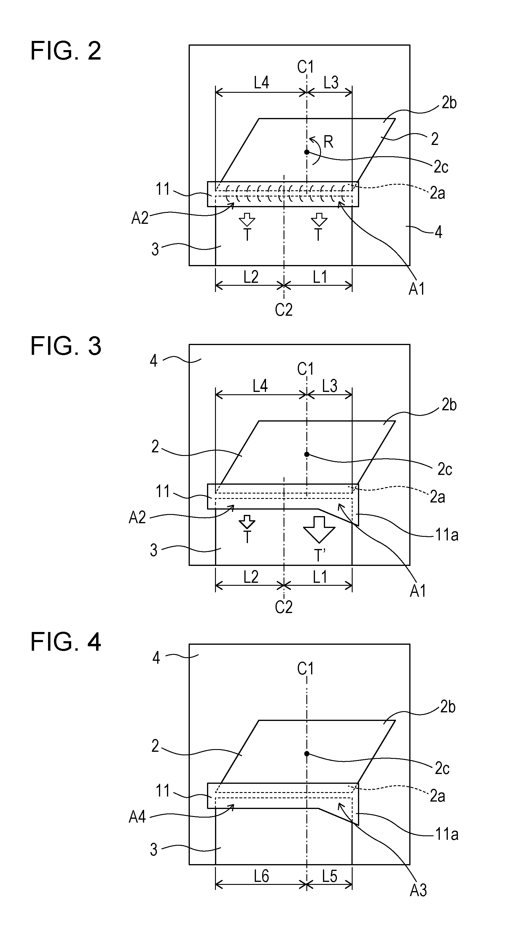
[0063]In the first and second embodiments, the length of the sealing member 11 extending along the side of the recording element substrate 2 adjacent to the first side portion 2a is substantially the same as the length of the sides thereof. However, this embodiment has a compact sealing member 11 shorter than the sides, as shown in FIG. 7A. In this configuration, the connecting members 10 (see FIGS. 1A to 1C) for electrically connecting the recording element substrate 2 and the electrical wiring substrate 3 are densely and partially disposed, and the sealing member 11 of a minimum size necessary for covering the connecting members 10 is provided. The sealing member 11 is disposed at a position biased in the direction along the side adjacent to the first side portion 2a of the recording element substrate 2 so that the perpendicular C1 passing through the center of gravity 2c of the recording element ...


PUM


Abstract

A liquid ejection head includes a recording element substrate including an electrode at a first side portion; an electrical wiring substrate having a wire line; a connecting portion connecting the electrode and the wire line; and a sealing material provided between the first side portion of the recording element substrate and the electrical wiring substrate. A first line and a second line are out of alignment in a direction along a side of the recording element substrate. The first line orthogonal to the side passes through a center of gravity of the recording element substrate. A second line passes through a center of a part covered with the sealing material and extends parallel to the first line. Of a part of the sealing material, a first area on the first line side has a larger volume than that of a second area opposite to the first line side.

Description

BACKGROUND OF THE INVENTION[0001]1. Field of the Invention[0002]The present invention relates to a liquid ejection head for ejecting liquid.[0003]2. Description of the Related Art[0004]Ink-jet (IJ) printers have recently been used not only for home printing but also for commercial printing, such as business printing and retail photo printing, and for industry printing, such as electronic circuit printing and panel display, and applications are spreading. Supporting high-speed printing is a strong requirement for IJ printer heads for use in commercial printing and industry printing. To meet the requirement, recording elements that generate energy for ejecting liquid ink are driven at high frequency, or a line head having a width larger than the width of a recording medium and having a large number of ejection ports is used.[0005]PCT Japanese Translation Patent Publication No. 2010-521343 discloses a configuration of a long line head in which a plurality of recording element substrate...

Claims


Application Information

Patent Timeline
Patent Type & Authority Patents(United States)
IPC IPC(8): B41J2/14B41J2/16
CPCB41J2/1433B41J2002/14491B41J2/14024B41J2/14072B41J2/14145B41J2202/11
Inventor TAMENAGA, ZENTAROMORIGUCHI, TAKUTOIWANAGA, SHUZOYAMADA, KAZUHIROMORIYA, TAKATSUGUYAMAMOTO, AKIRA
Owner CANON KK
Learn More