Optical pickup and optical disk apparatus

a technology of optical disk and optical pickup, which is applied in the direction of data recording, instruments, disposition/mounting of heads, etc., can solve the problems of reducing reducing the size, and reducing the cost of components/parts, so as to achieve easy correction, reduce the number of components/parts, and high thermal conductivity

Inactive Publication Date: 2005-12-22
SONY CORP
View PDF1 Cites 1 Cited by
  • Summary
  • Abstract
  • Description
  • Claims
  • Application Information

AI Technical Summary

Benefits of technology

[0019] Suppose that the temperature gradient in the objective lens portions positioned on the circumferences having the same radius is substantially zero, as described above. In this case, coma aberrations, astigmatism, and the like as optical aberrations occurring in the objective lens are very low so as to be negligible. Consequently, it is sufficient to take into account only spherical aberrations. Spherical aberrations can be easily corrected for by the optical system of the optical pickup.
[0020] Accordingly, different from the past case, the occurrence of the temperature gradient in the objective lens can be restrained without an annular member formed of a material having high thermal conductivity being interposed between the objective lens and the lensholder. Consequently, the number of component...

Problems solved by technology

However, in the above-described pickup, since the annular member is provided to the lensholder, the number of components/parts increases, thereby producing disadvantages in implementing a size reduction of the optical pickup and a cost reduction therefor.
In addition, since the a...

Method used


Image

  • Optical pickup and optical disk apparatus
  • Optical pickup and optical disk apparatus
  • Optical pickup and optical disk apparatus

Examples


Embodiment Construction

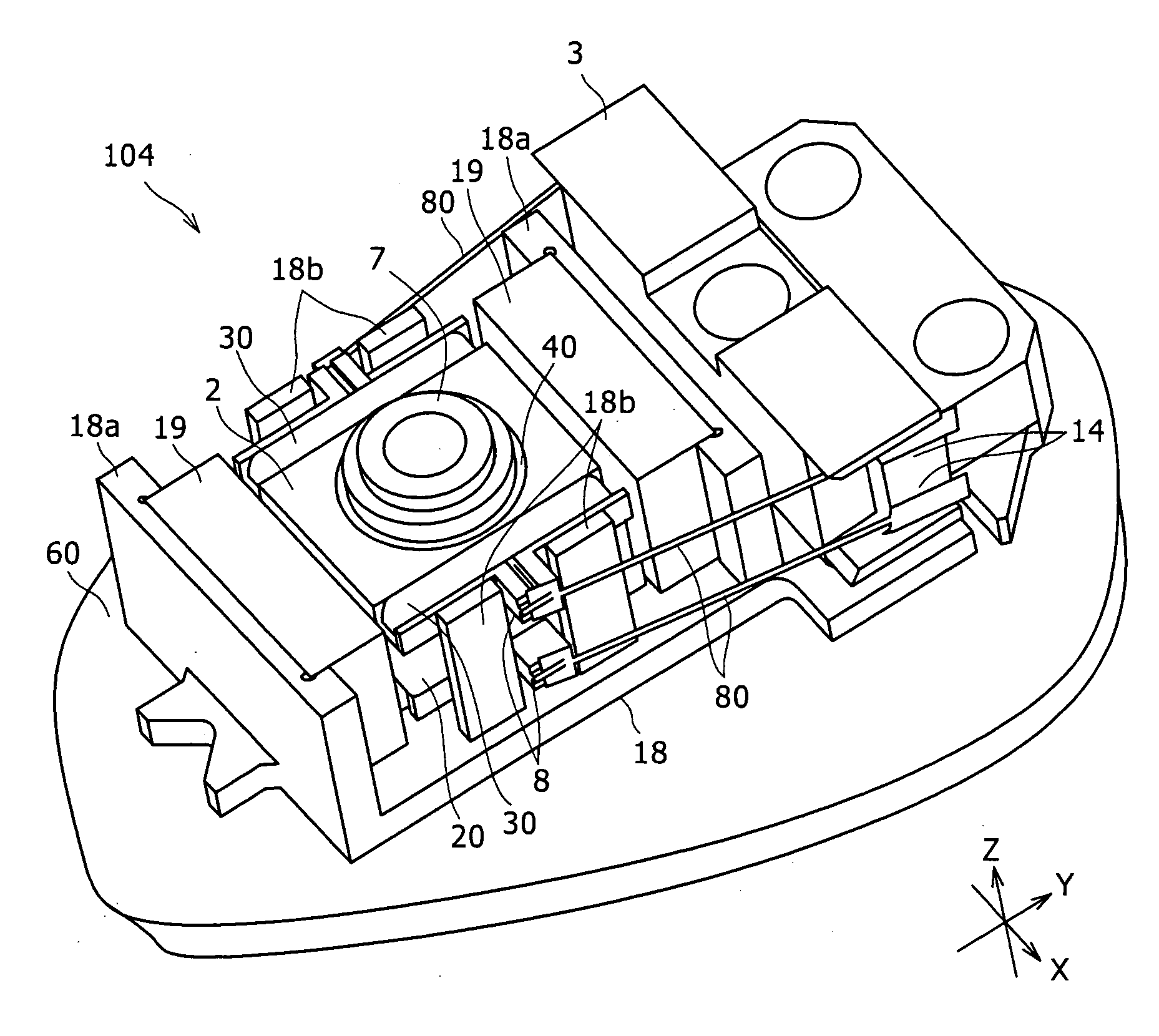
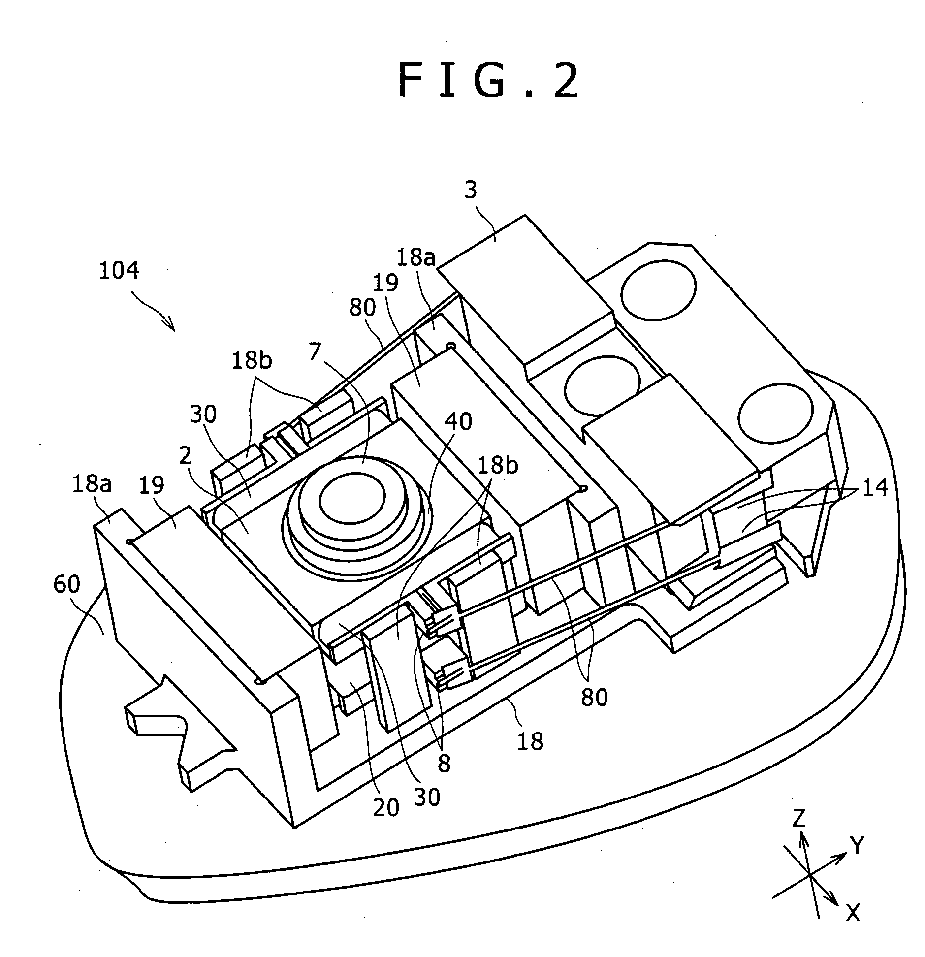
[0027] In the present invention, it is intended that a size reduction and a cost reduction are implemented, and the occurrence of optical aberrations attributed to temperature gradients in an objective lens is prevented without sacrificing response characteristics. This is implemented by providing a layer having thermal conductivity between an inner peripheral surface of a lensholder and an outer peripheral surface of the objective lens and between a bottom wall of the lensholder and a lens surface of the objective lens.

[0028] Embodiments of an optical pickup and a recording and reproducing apparatus will be described hereinbelow with reference to the drawings.

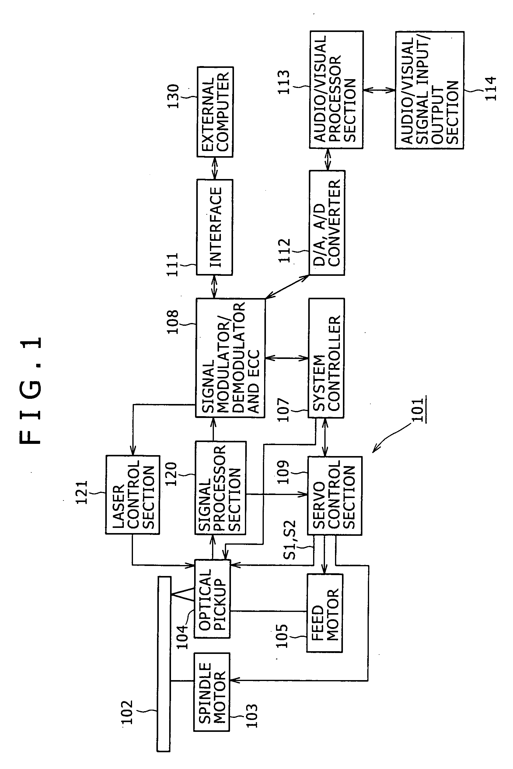
[0029]FIG. 1 is a block diagram showing the configuration of an optical disk apparatus including an optical pickup assembled thereinto, according to an embodiment of the present invention.

[0030] With reference to FIG. 1, an optical disk apparatus 101 includes a spindle motor 103 serving as driving means that performs rotati...


PUM


Abstract

A lensholder has one focus coil and two tracking coil. The lensholder has an accommodation recess portion accommodating an objective lens. A layer having thermal conductivity is provided between an inner peripheral surface of the lensholder and an outer circumferential surface of the objective lens and between a bottom wall of the lensholder and a one-side lens surface. The objective lens is bonded by an adhesive and is thereby mounted in a state where the layer is interposed individually between the inner peripheral surface of the lensholder and the outer circumferential surface of the objective lens and between the bottom wall of the lensholder and the one-side lens surface.

Description

CROSS REFERENCES TO RELATED APPLICATIONS [0001] The present invention contains subject matter related to Japanese Patent Application JP 2004-180039 filed in the Japanese Patent Office on Jun. 17, 2004, the entire contents of which being incorporated herein by reference. BACKGROUND OF THE INVENTION [0002] 1. Field of the Invention [0003] The present invention relates to an optical disk apparatus that performing operations such as recording and reproduction of a signal on an optical disk and to an optical pickup for use in the LCD device. [0004] 2. Description of the Related Art [0005] Optical pickups perform the operation of recording or reproduction or the operations of recording and reproduction of signals by irradiating optical beams on, for example, a CD (compact disk) and a DVD (digital versatile disk). [0006] An optical pickup of this type includes a lensholder holding an objective lens. The lensholder includes a focus coil provided to move the lensholder in a focus direction, ...

Claims


Application Information

Patent Timeline
IPC IPC(8): G11B7/00G11B7/09G11B7/135
CPCG11B7/0935
Inventor YAMAGISHI, MASATO
Owner SONY CORP
Why Eureka
Try Eureka