Multipole lens and method of fabricating same
a multi-pole lens and fabrication method technology, applied in the field of multi-pole lenses, can solve the problems of accumulating machining errors, unable to perform circular assembly reference machining using wire electric discharge machining, and unable to make the step of machining an assembly reference common with the step, so as to achieve the effect of improving accuracy
- Summary
- Abstract
- Description
- Claims
- Application Information
AI Technical Summary
Benefits of technology
Problems solved by technology
Method used
Image
Examples
embodiment 1
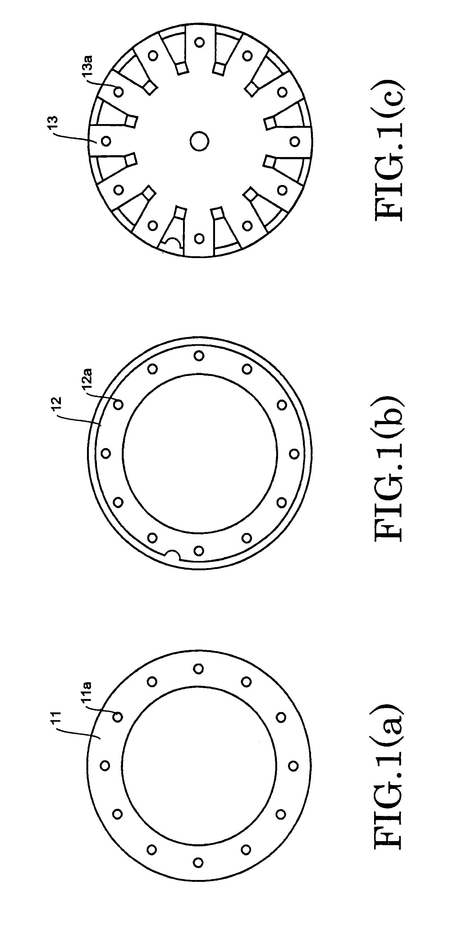
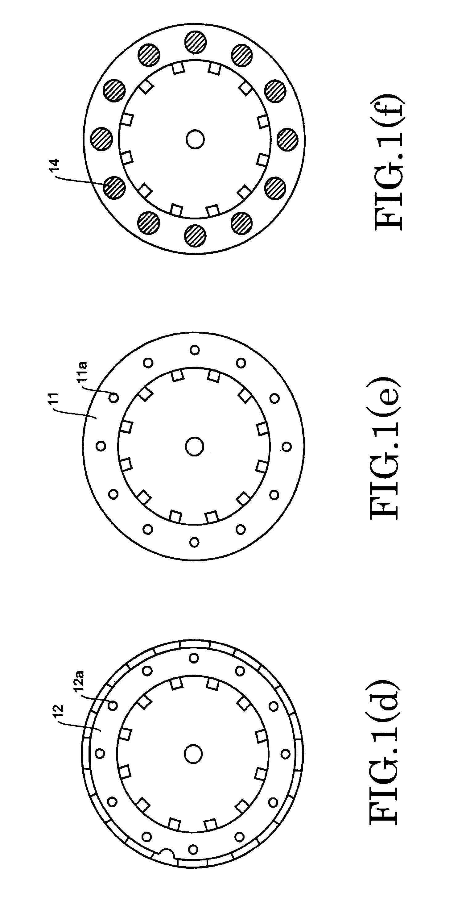
[0050]A procedure for assembling a blank member that is a workpiece machined by electric discharging is described by referring to FIGS. 1(a) through 1(f). Step 1 is shown in FIG. 1(a). A ring 11 is made of a nonmagnetic material, such as a copper alloy. The ring 11 is provided with holes 11a for injecting a curing agent 14 (described later). In the following description, the curing agent is an epoxy resin curing agent. Step 2 is shown in FIG. 1(b). A film-like insulating material (hereinafter referred to as the insulator) 12 is placed on the ring 11. The insulator 12 is provided with holes 12a for injecting the curing agent. In this case, the holes 12a are aligned with the holes 11a in the ring 11.
[0051]Step 3 is shown in FIG. 1(c). A blank material 13 from which polar elements will be fabricated is made of a soft magnetic material. The blank material 13 is provided with holes 13a for injecting the epoxy resin curing agent. The blank material 13 is placed on the insulator 12 such th...
embodiment 2
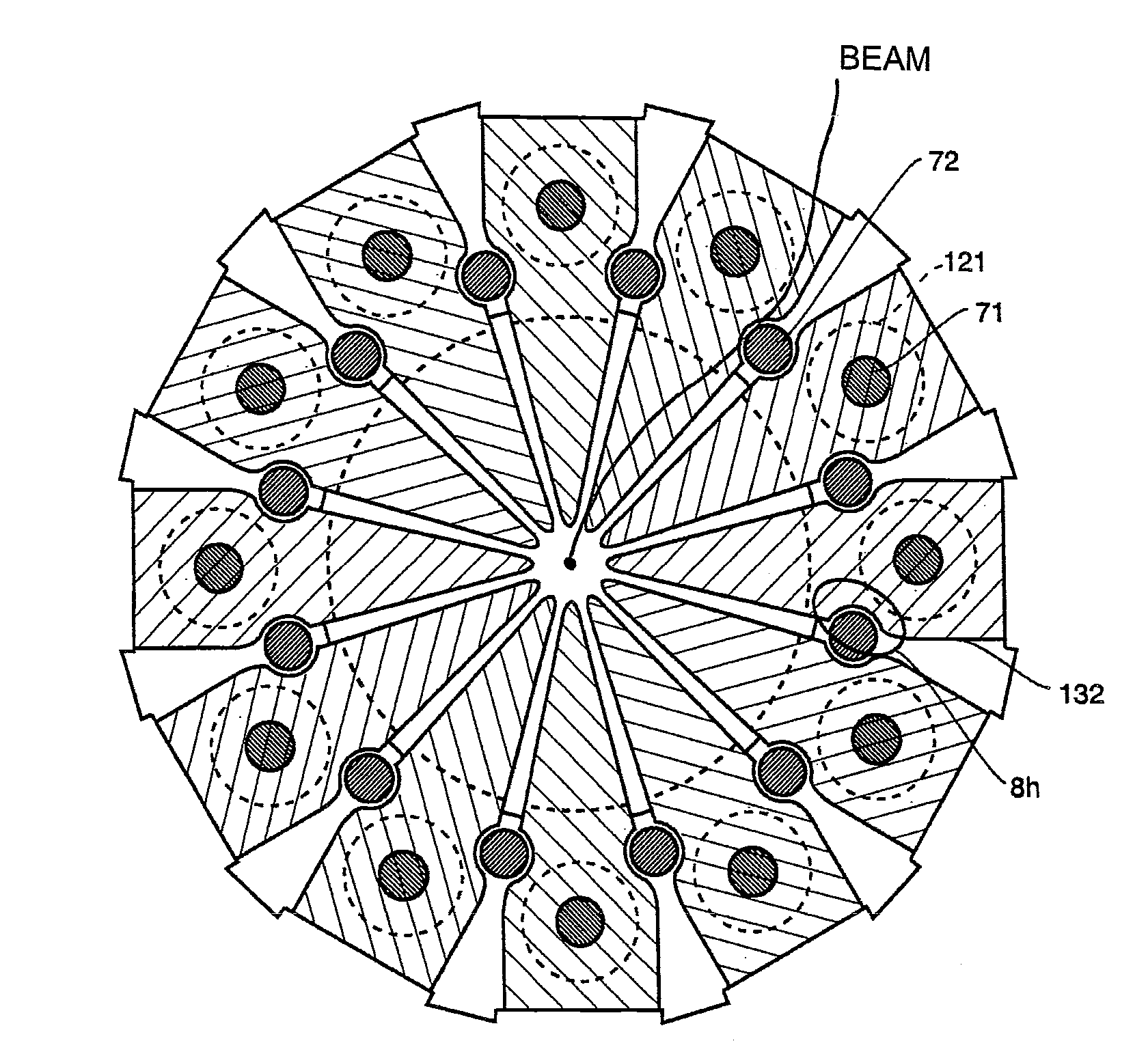
[0062]A blank member is fabricated by steps 1-6 already described in connection with FIGS. 1(a) through 1(l) in the same way as in Embodiment 1. A procedure of machining the blank member is described by referring to the plan views of FIG. 1(j) and FIG. 1(k). FIG. 1(j) and FIG. 1(k) illustrate steps 7 and 8, respectively. The blank member integrated by step 6 is set on a wire electric discharge machine (not shown) and the outer contour is machined. Because of this machining step, the discontinuous shapes of arcs 111a providing an assembly reference, slot 61, and terminal ends of the polar elements are machined.
[0063]In step 8, the multipolar element is divided by wire electric discharging subsequently to step 7, and the shapes of front ends of polar elements are formed. The portion of the multipolar element which is placed in a vacuum is completed. FIG. 1(l) is a horizontal cross section of the portion of the multipolar element which is placed in a vacuum, and shows the manner in whi...
embodiment 3
[0071]Two or more slots are formed by a machining step. The number of the slots is less than the number of the polar elements. Thus, any one of the slots which gives a high positional accuracy with the azimuthal orientation of the polar elements can be selected during assembly, and the accuracy of the azimuthal angle of the polar elements can be improved.
PUM
 Abstract
Description
Claims
Application Information
 - R&D
- Intellectual Property
- Life Sciences
- Materials
- Tech Scout
- Unparalleled Data Quality
- Higher Quality Content
- 60% Fewer Hallucinations
Browse by: Latest US Patents, China's latest patents, Technical Efficacy Thesaurus, Application Domain, Technology Topic, Popular Technical Reports.
© 2025 PatSnap. All rights reserved.Legal|Privacy policy|Modern Slavery Act Transparency Statement|Sitemap|About US| Contact US: help@patsnap.com


