Q-pole type mass spectrometer

a mass spectrometer and q-pole technology, applied in the field of mass spectrometers, can solve the problems of reducing the concentration of gas to be measured, affecting the accuracy of q-pole ions, so as to achieve the same position accuracy tremendously easily

Inactive Publication Date: 2007-05-24
SHIOKAWA YOSHIRO
View PDF8 Cites 0 Cited by
  • Summary
  • Abstract
  • Description
  • Claims
  • Application Information

AI Technical Summary

Benefits of technology

[0061] Further, because the length of the Q-pole may be reduced to one of several parts of that of the conventional Q-pole type mass spectrometer, the same accuracy of position can be achieved tremendously easily. The problem with the accuracy in position of the Q-pole, which is a serious obstacle in terms of performance and cost in the conventional Q-pole type mass spectrometer, can be solved by the present invention.

Problems solved by technology

Anyway, deceleration including stop and retraction is generated by a collision with the atmospheric gas so that advance of an ion in the Q-pole is hampered.
With this complicated structure, there not only occurs a problem about cost and reliability, but there also occurs a problem in that the concentration of gas to be measured is reduced so that the sensitivity is deteriorated.
Thus, this is a serious problem.
However, because the length of the Q-pole is short, the interval between the poles needs to be less than 1 mm and therefore the required positional accuracy of the Q-pole becomes very strict.
Thus, currently, a sufficient performance cannot be achieved so that difficulty and cost of production increase.
On the other hand, the ordinary Q-pole type mass spectrometer has a serious fringing problem which deteriorates the sensitivity for a high-mass molecule.
The fringing problem is generated because the electric field near an end face (fringing) of the Q-pole is weaker and disturbed more than near the center of the Q-pole.
That is, if the ion speed is slow, the time in which ion sojourns in the fringing region is prolonged, so that unstable vibration is repeated, thereby increasing the bad influence.
It has been experimentally known that if the vibration in the fringing region is once or more, the bad influence is increased rapidly.
It is known that an ion having the same linear energy is slower if the mass thereof is increased, so that the fringing problem becomes very serious in the case of high mass.
However, the vibration frequency becomes short in the above mass separation so that a necessary resolution cannot be obtained.
However, not only is the structure complicated, but there also occurs a new problem in that performance is deteriorated by a disturbance of the electric field between the Q-poles of respective segments.
But there is a new problem JP-A-48-41791 in that the nozzle disturbs the electric field (data that it is ⅕ at 100 amu and 1 / 100 at 300 amu as the before described is a result of this nozzle system).
However, actually, this method has not produced any effect.
The first reason is that a large difference is generated between the potential on the axis in the Q-pole and the potential out of the Q-pole, so that the DC potential component is greatly disturbed whereby the bad influence of the fringing is further intensified.
If the electric field exists in the axial direction the ion is decelerated and if the electric field in the axial direction is not completely uniform in a section vertical to the axis, a bad influence is produced.
Particularly, this decelerating electric field is formed with symmetric electric fields comprised of the quadrupole electric field at the Q-pole and a uniform electric field (non electric field) outside of the Q-pole, so its section does not become uniform and the electric field is greatly disturbed.
Anyway, conventionally, there was no effective countermeasure for the fringing problem and there was not any Q-pole type mass spectrometer capable of measuring high-mass molecules at a high sensitivity.
But, in the ion trap, ions sojourn in the same region, so that a number of ions cannot be measured at the same time and its dynamic range is small owing to an influence of space charge.
Further, in the ion trap, ion deposition and mass sweep are carried out alternately, so that complicated control is necessary and the ion source has no expandability.
This point is quite different from a magnetic field deflection type mass spectrometer in which, if an ion trace is changed halfway, a necessary initial condition is lost so that subsequent mass separation is completely impossible.
If this particle (charged particle) is an ionized gas molecule (ion), the time in which the ion passes the Q-pole region is extremely prolonged, so that it is never actually used as a measuring device.
As a result, the quadrupole electric field is inevitably disturbed so that proper mass separation is impossible.
Further, according to this method, the driving mechanism is reciprocated along the Q-pole region so that the charged particle cannot be transported out of the Q-pole region.
Therefore, this method is far from practical use as a mass spectrometer.
Therefore, the application of the particle transportation method by the quadrupole rail to the Q-pole type mass spectrometer is completely impossible from the viewpoints of performance and practical use.
But continuous mass separation for gas molecules can not be carried out by the known method.
If an ion is injected at high speed in order to reduce the influence of an end electric field near a Q-pole end face (fringing) which deteriorates the sensitivity of the Q-pole type mass spectrometer, the ion passes the Q-pole region at high speed, so that the necessary vibration frequency cannot be obtained and proper mass separation is not carried out.
Further, there is also a problem in that a condensation function cannot be carried out so that an ultra-small amount of gas cannot be measured.

Method used


Image

  • Q-pole type mass spectrometer
  • Q-pole type mass spectrometer
  • Q-pole type mass spectrometer

Examples


first embodiment

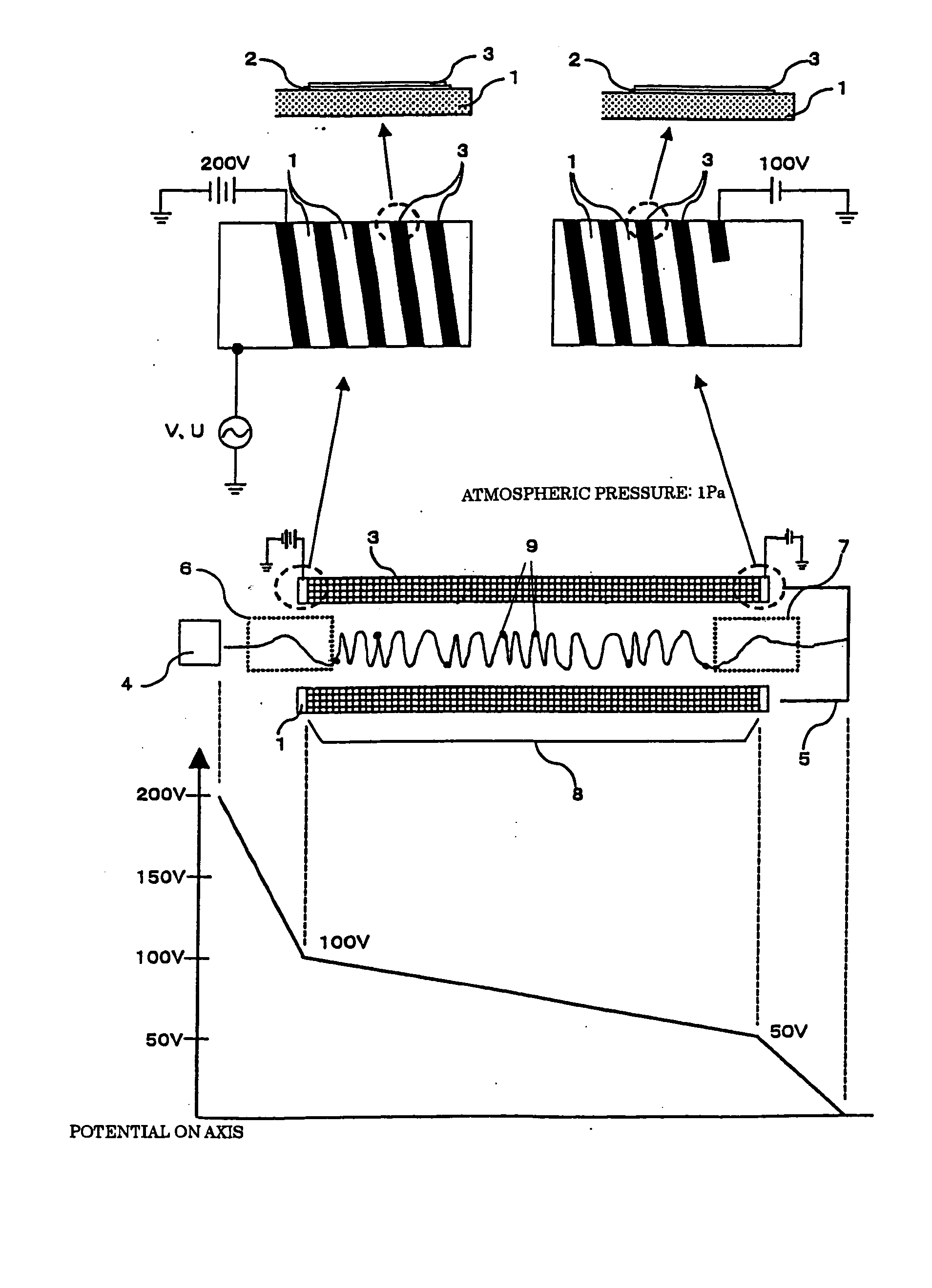
[0073]FIG. 1 is a schematic diagram for explaining a first embodiment of the present invention. The Q-pole type mass spectrometer which will be described in this embodiment can be actuated in a high-pressure atmosphere and is capable of measuring high-mass molecules with a high sensitivity. Control of motion of an ion to be measured in the Q-pole region in the axial direction is carried out by Coulomb force generated by an electric field formed by four Q-poles composing a Q-pole type mass spectrometer. Each Q-pole of the four Q-poles has different DC potentials at respective positions in the axial direction, while they have an equal DC potential except DC voltage U at the same position in the axial direction of each Q-pole of the four Q-poles.

[0074] The basic structure of the Q-pole type mass spectrometer of the present embodiment is the same as a conventional one, so that description thereof is omitted. The length of a Q-pole 1 can be designed 100 to 300 mm like the conventional Q...

second embodiment

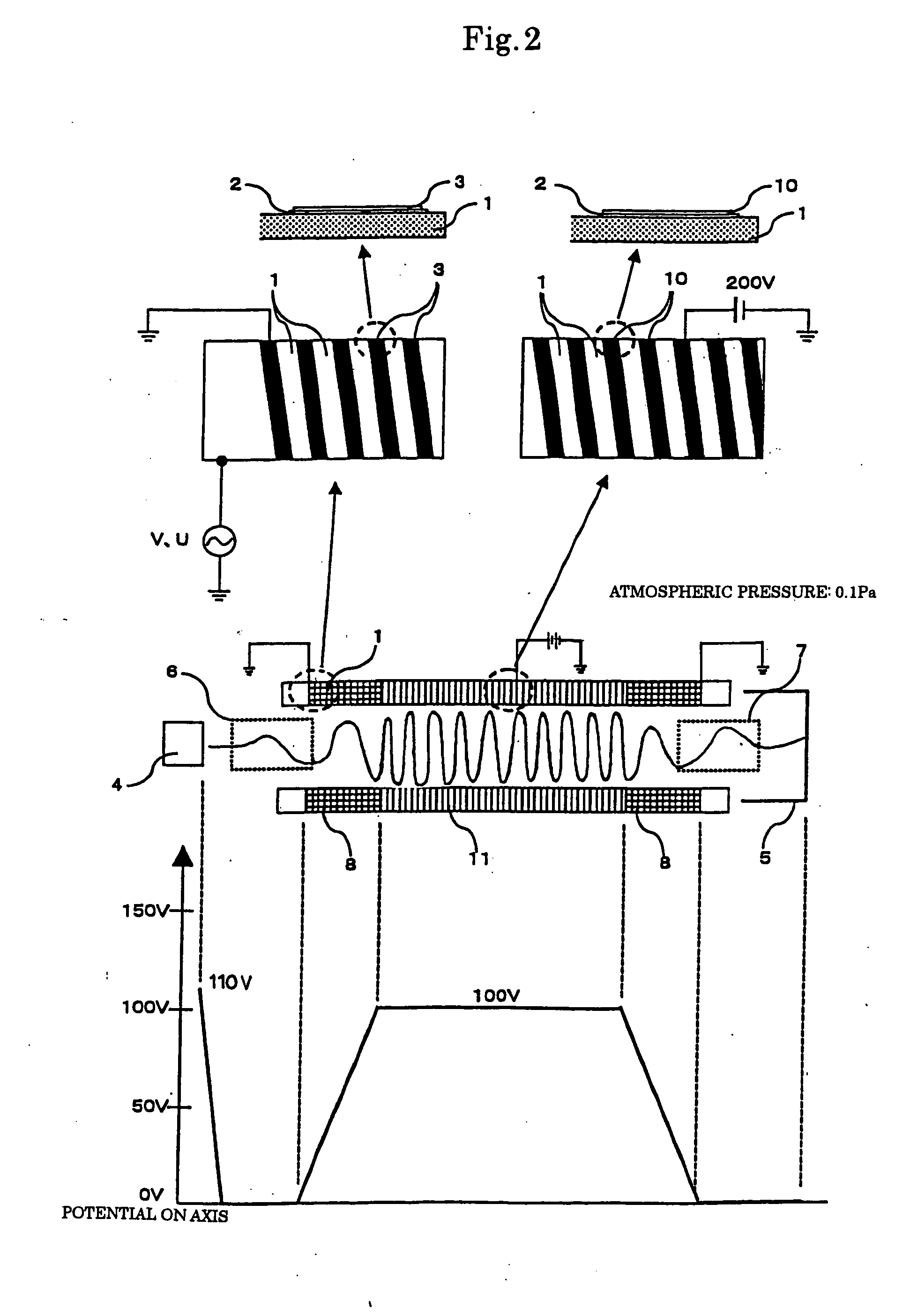
[0088]FIG. 2 is a schematic diagram for explaining a second embodiment of the present invention. The Q-pole type mass spectrometer which will be described in this embodiment is capable of measuring high-mass molecules with a high sensitivity. Control of motion of ions to be measured in the Q-pole region in the axial direction is carried out by Coulomb force generated by an electric field formed by four Q-poles composing the Q-pole type mass spectrometer. Each Q-pole of the four Q-poles has different DC potentials at respective positions in the axial direction, while they have an equal DC potential except DC voltage U at the same position in the axial direction of each Q-pole of the four Q-poles.

[0089] The Q-pole type mass spectrometer of this embodiment is different from that of the first embodiment only in that a conductive thin film 10 is added to the Q-pole 1, the voltage application condition is different, and that the pressure of the atmospheric gas is less than 0.1 Pa. The ot...

third embodiment

[0098]FIG. 3(a) is a schematic diagram for explaining a third embodiment of the present invention. The Q-pole type mass spectrometer which will be described in this embodiment can be actuated in a high-pressure atmosphere and controls the motion of an ion to be measured in the Q-pole region in the axial direction by a reaction force generated by a collision between the ion to be measured and the atmospheric gas.

[0099] The Q-pole type mass spectrometer of this embodiment has the same structure as the conventional Q-pole type mass spectrometer except that the ion source 4 and the collector 5 are so constructed that gas passes through them and a carrier gas flows therein.

[0100] The pressure of the atmospheric gas as the carrier gas is about 1 Pa. The carrier gas flows in the Q-pole in the direction of ion advancement as indicated by reference numeral 14. In the Q-pole type mass spectrometer of this embodiment, the ion receives a reaction force each time it collides with the carrier g...


PUM

PropertyMeasurementUnit
pressureaaaaaaaaaa
lengthaaaaaaaaaa
lengthaaaaaaaaaa

Abstract

A Q-pole type mass spectrometer can be used under a high-pressure atmosphere of more than 0.1 Pa. The Q-pole type mass spectrometer can analyze the mass of gas molecules continuously, and can separate mass properly even if an ion is injected at high speed in order to reduce the influence of an end electric field near an end face (fringing) of the Q-pole. The motion of the ions to be measured in the diameter direction is independent of the motion of ions in the axial direction within the Q-pole region of the Q-pole type mass spectrometer. In the Q-pole type mass spectrometer installed in a reduced pressure atmosphere, the motion of ions to be measured in the axial direction advancing from an ion source toward a collector, is controlled within the Q-pole region so as to separate the mass of the ions to be measured by Coulomb force generated by a quadrupole high-frequency electric field in the diameter direction.

Description

BACKGROUND OF THE INVENTION [0001] This is a Continuation Application of U.S. patent application Ser. No. 10 / 887,910, filed Jul. 12, 2004, which is a Continuation Application of U.S. patent application Ser. No. 09 / 824,211, filed Apr. 3, 2001.FIELD OF THE INVENTION [0002] The present invention relates to a mass spectrometer for measuring the mass of a gas molecule in a reduced-pressure (vacuum) atmosphere. More particularly, the present invention relates to a mass spectrometer which can be used in a relatively high pressure atmosphere of 0.1 Pa or more, a small-size mass spectrometer capable of measuring a high-mass molecule at a high sensitivity, and a mass spectrometer capable of measuring an ultra fine amount of gas. PRIOR ART [0003] A Q-pole type mass spectrometer, called mass filter or quadrupole type mass analyzer, is capable of carrying out high-sensitivity measurement in a wide dynamic range with a small and simple structure under easy control. Therefore, the Q-pole type mass...

Claims


Application Information

Patent Timeline
Patent Type & Authority Applications(United States)
IPC IPC(8): B01D59/44G01N27/62H01J49/42
CPCH01J49/4215
Inventor SHIOKAWA, YOSHIRO
Owner SHIOKAWA YOSHIRO
Why Eureka
Try Eureka