Method for operating a vehicle drive train having an internal combustion engine

a technology of internal combustion engine and drive train, which is applied in the direction of mechanical equipment, transportation and packaging, etc., can solve the problems of time-consuming, unsatisfactory shifting comfort, and undesirable increase both of production costs and fitting space occupied by the transmission, and achieves the effect of high shifting comfor

Active Publication Date: 2015-12-22
ZF FRIEDRICHSHAFEN AG
View PDF26 Cites 3 Cited by
  • Summary
  • Abstract
  • Description
  • Claims
  • Application Information

AI Technical Summary

Benefits of technology

[0009]Thus, the purpose of the present invention is to provide a method for operating a vehicle drive-train, by means of which gearshifts in transmission systems, in which at least one interlocking shifting element is involved, can be carried out within predefined shifting times with high shifting comfort, inexpensively, and without requiring additional fitting space for the transmission.
[0011]In this way, when a shift has been called for, an interlocking shifting element of a transmission to be engaged, is synchronized before its closing process without additional designed synchronization devices, by appropriate operation of the internal combustion engine, inexpensively and with little space occupation by the transmission, so that gearshifts can be carried out with high shifting comfort along with acceptable shifting times.
[0013]Since in the neutral operating condition of the transmission, even without a corresponding shift command the interlocking shifting element is already changed to and held in its closed operating condition, the transmission can be operated with a high level of spontaneity. The further shifting element is also involved in obtaining the gear for reverse driving, so that on arrival of a corresponding shift command, starting from the neutral operating condition a shift to the starting gear or first gear for forward driving or to the gear for reversing can in each case be carried out with a short shifting time.

Problems solved by technology

As is known per se, since owing to drag losses that occur in the area of open frictional shifting elements such transmission systems can only be operated with inadequate efficiencies, certain frictional shifting elements are replaced by interlocking shifting elements.
Disadvantageously, compared with frictional shifting elements, interlocking shifting elements with or without additionally designed synchronization means can only be shifted comfortably when their speed differences are very small, i.e. close to their synchronous speed, and accordingly the operation of a transmission constructed with at least one interlocking shifting element and designed as an automatic transmission is made undesirably more difficult, at least when carrying out some shifts in which an interlocking shifting element is involved.
However, additional design measures for synchronizing interlocking shifting elements of transmission systems in order to carry out a required shift within an acceptable shifting time along with a high level of shifting comfort entail an undesirable increase both of production costs and of the fitting space occupied by the transmission.
Disadvantageously, in this geared change-speed transmission no shifting element must be closed in the neutral condition, so that on shifting from neutral into a gear an interlocking shifting element must first be engaged, with prior adaptation of the engine speed, which is time-consuming.

Method used


Image

  • Method for operating a vehicle drive train having an internal combustion engine
  • Method for operating a vehicle drive train having an internal combustion engine
  • Method for operating a vehicle drive train having an internal combustion engine

Examples


Embodiment Construction

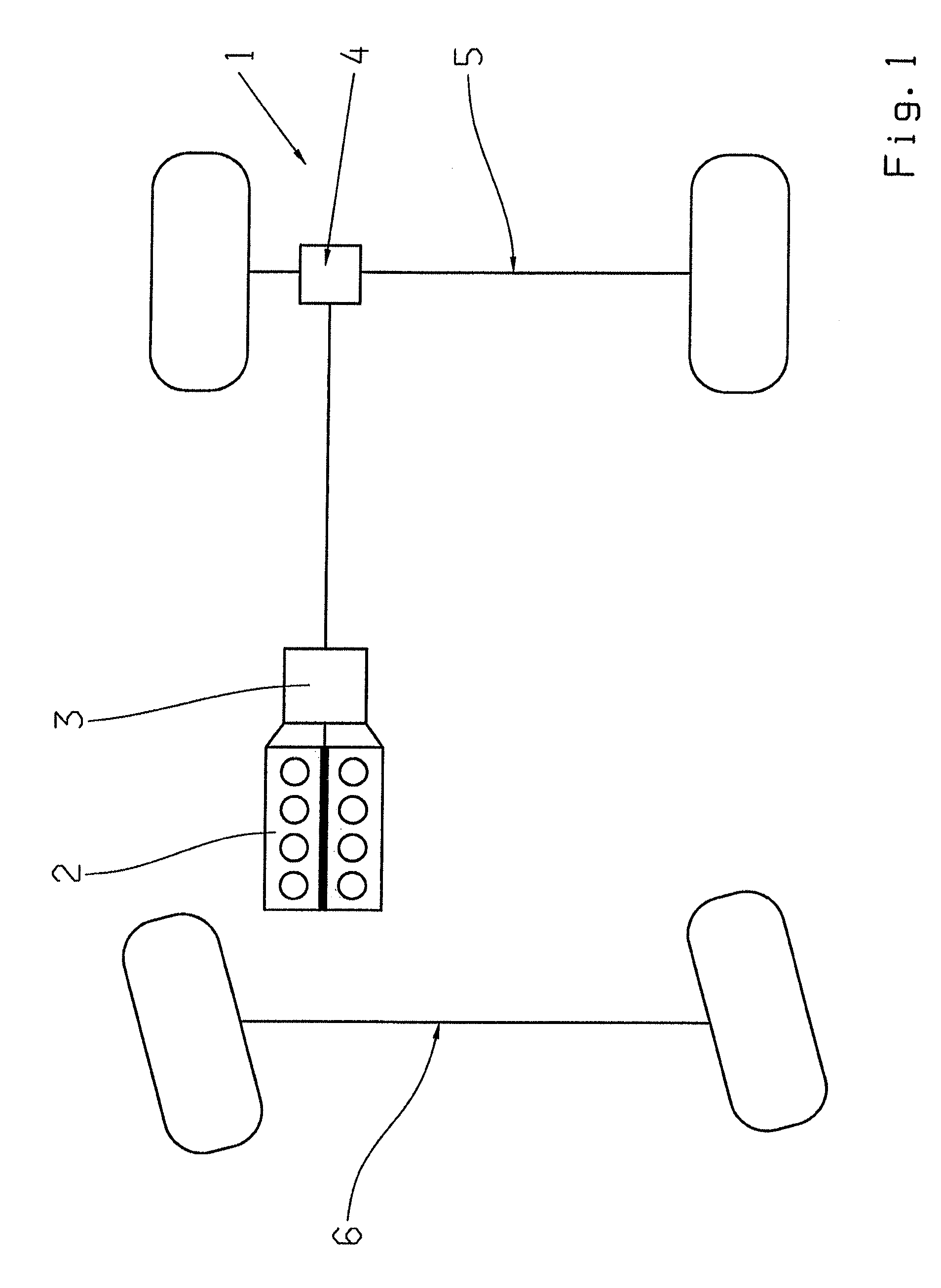
[0024]FIG. 1 shows a vehicle drive-train 1 with an internal combustion engine 2, a transmission 3, by means of which various gear ratios for forward and reverse driving can be obtained, and with a transfer transmission unit 4 and two vehicle axles 5, 6 such that in this case the vehicle axle 5 is the rear axle and the vehicle axle 6 is the front axle of the vehicle.

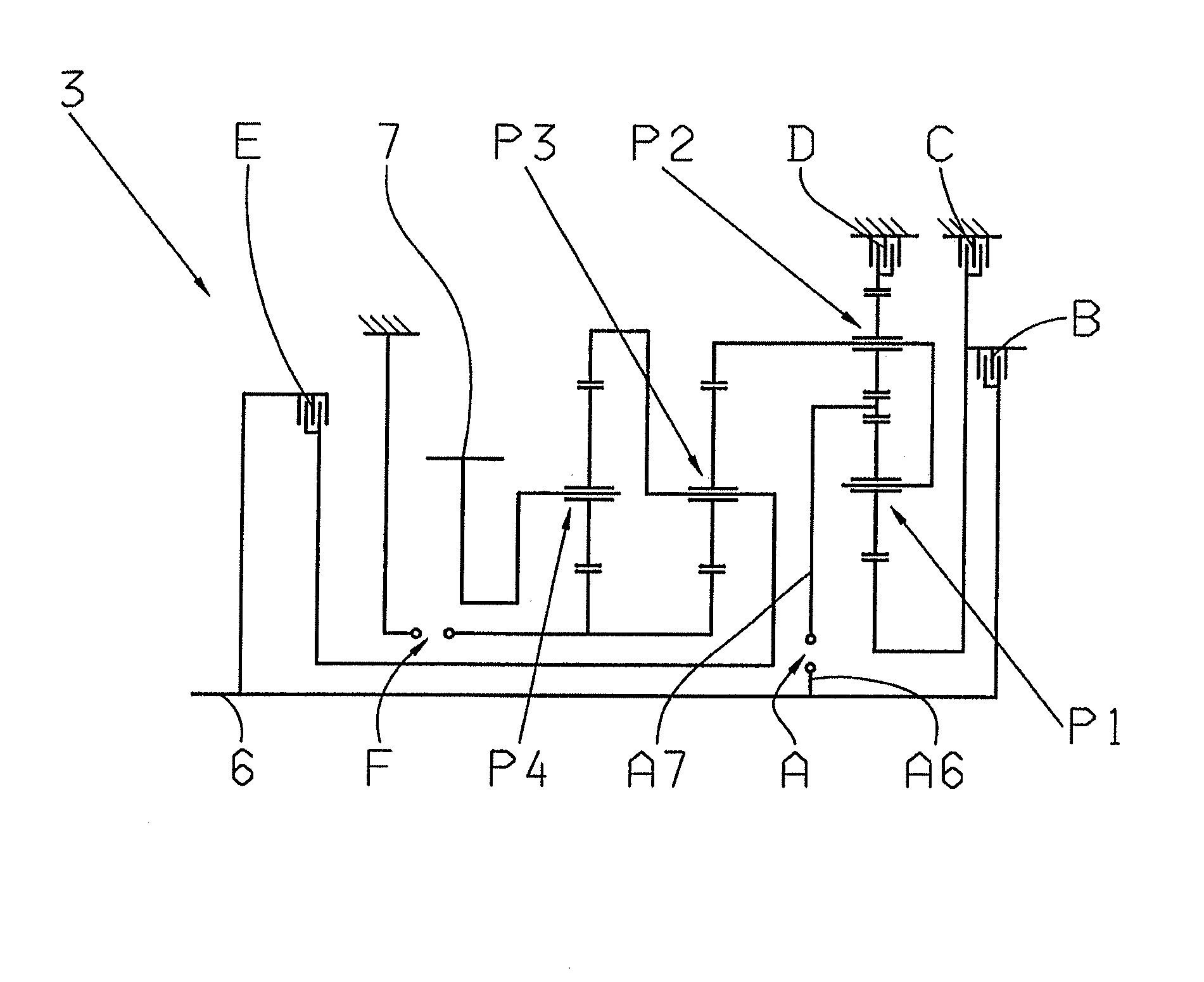
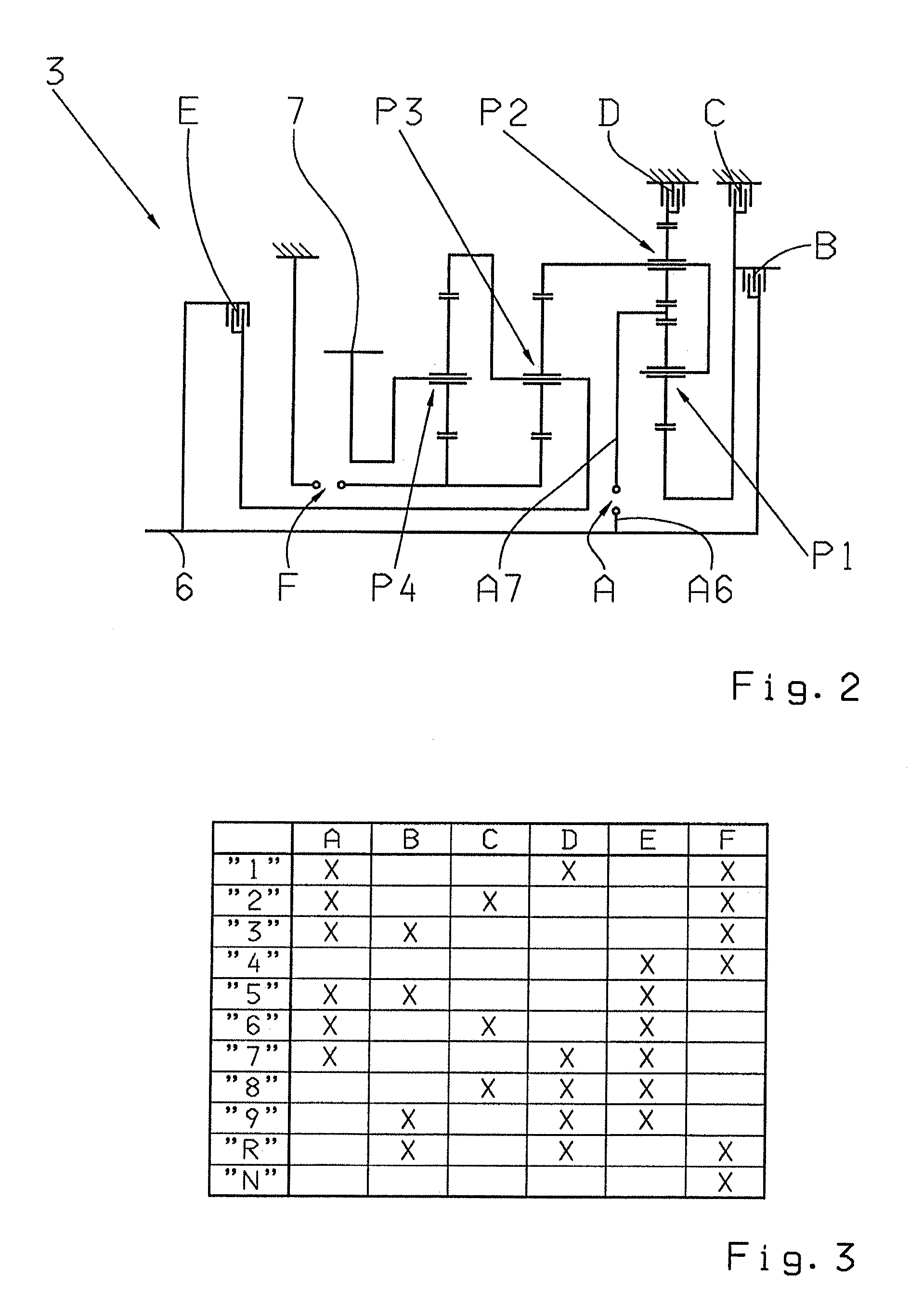
[0025]A gear layout of the transmission 3 or a multi-step transmission, which is basically known from the unpublished German patent application DE 10 2008 000 429.4 by the present applicant, is represented in FIG. 2. The transmission 3 comprises a transmission input shaft 6 and a transmission output shaft 7, which when mounted in the vehicle is connected to the transfer transmission unit 4 whereas the transmission input shaft 6 is functionally connected to the internal combustion engine 2.

[0026]In addition the transmission 3 comprises four planetary gearsets P1 to P4, such that the first and second planetary gearsets P1, ...


PUM


Abstract

A method of operating a vehicle drive-train comprising an internal combustion engine and a transmission system functionally connected to the internal combustion engine. The transmission has an interlocking shifting element, one shifting element half of which is functionally connected to the transmission input shaft while the other shifting element half is functionally connected to a transmission output shaft. Upon receipt of a command to change the transmission from a neutral position, in which a force flow through the transmission is interrupted, to an operating condition, in which the force flow through the transmission is produced, the interlocking shifting element is changed to an engaged operating condition. A speed difference between the shifting element halves is brought by varying the speed of the internal combustion engine into a speed difference window within which the interlocking shifting element can be changed to its engaged operating condition.

Description

[0001]This application is a National Stage completion of PCT / EP2010 / 070383 filed Dec. 21, 2010, which claims priority from German patent application serial no. 10 2010 000 860.5 filed Jan. 13, 2010.FIELD OF THE INVENTION[0002]The invention concerns a method for operating a vehicle drive-train that comprises an internal combustion engine.BACKGROUND OF THE INVENTION[0003]Vehicle drive-trains known from the prior art are usually formed in each case by an internal combustion engine and at least one transmission system arranged between the internal combustion engine and a drive output, by means of which gear ratios called for in each case depending on the operating situation can be obtained.[0004]Such transmission systems, which are known per se and are made as automatic transmissions, are constructed with shifting elements for obtaining the various gear ratios, by means of the shifting elements, an applied torque can be transmitted by friction. When the engagement of a defined gear is c...

Claims


Application Information

Patent Timeline
Patent Type & Authority Patents(United States)
IPC IPC(8): B60W10/06F16H61/04F16H61/686F16H63/50F16H3/44F16H3/66
CPCF16H61/0403F16H3/66F16H61/686F16H63/502F16H2003/442F16H2061/0474Y10T477/677F16H2200/0065F16H2200/2012F16H2200/2046F16H2200/2064F16H2200/2094F16H2061/0488
Inventor HERBETH, VALENTINEARNOLD, JORGMIHATSCH, GEORGSCHMIDT, ANDREAS
Owner ZF FRIEDRICHSHAFEN AG
Why Eureka
Try Eureka