Friction ring, synchronizer ring, synchronizing unit as well as a variable gear transmission for a vehicle

a technology of synchronizer ring and friction ring, which is applied in the direction of belt/chain/gearing, clutch, belt element, etc., can solve the problems of increasing complexity, cost and not least, the weight of the corresponding transmission, and the natural limit of the minimization of the conical angle, so as to achieve the effect of high shifting comfort and simplified installation of the friction ring

Active Publication Date: 2018-01-09
OERLIKON FRICTION SYST GERMANY
View PDF34 Cites 1 Cited by
  • Summary
  • Abstract
  • Description
  • Claims
  • Application Information

AI Technical Summary

Benefits of technology

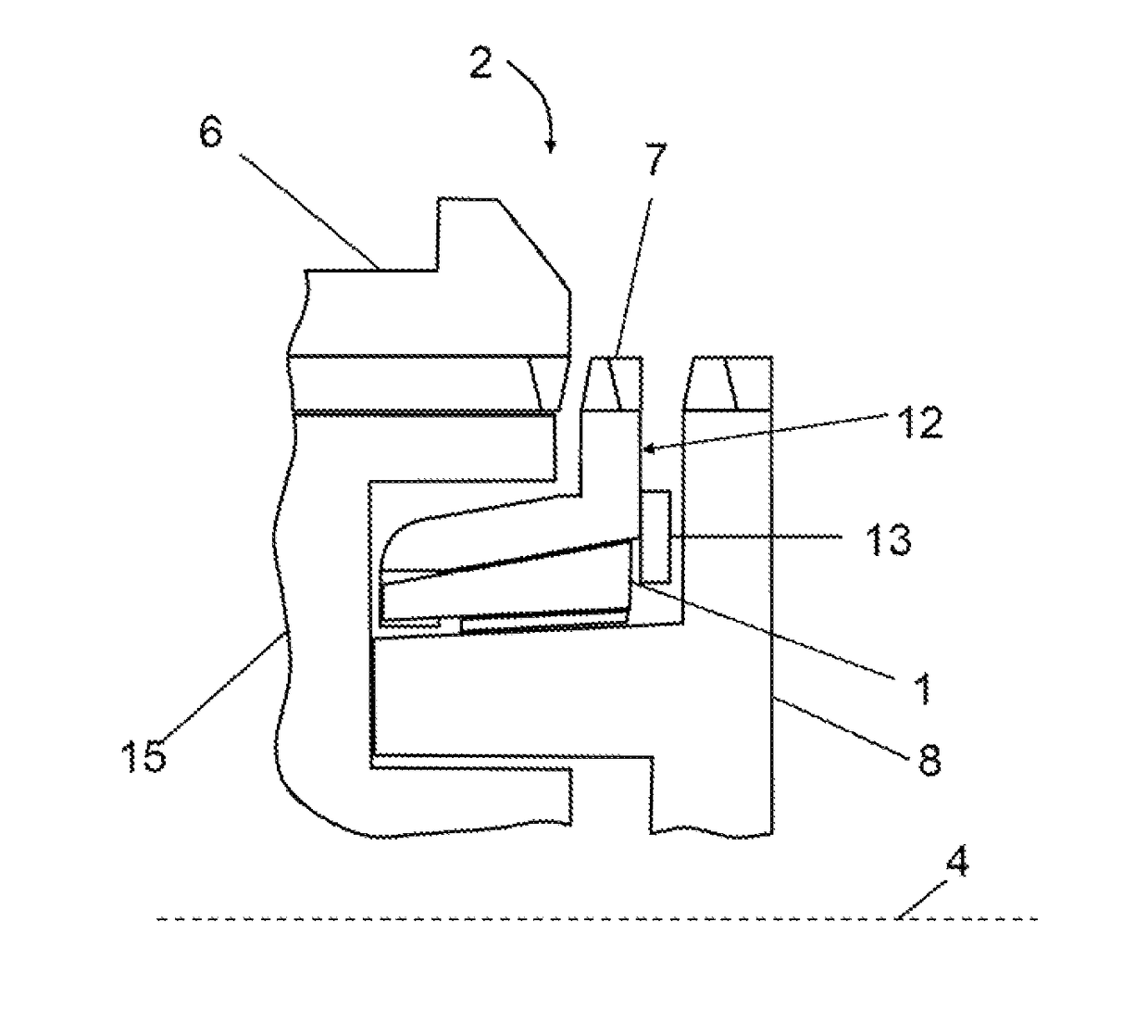
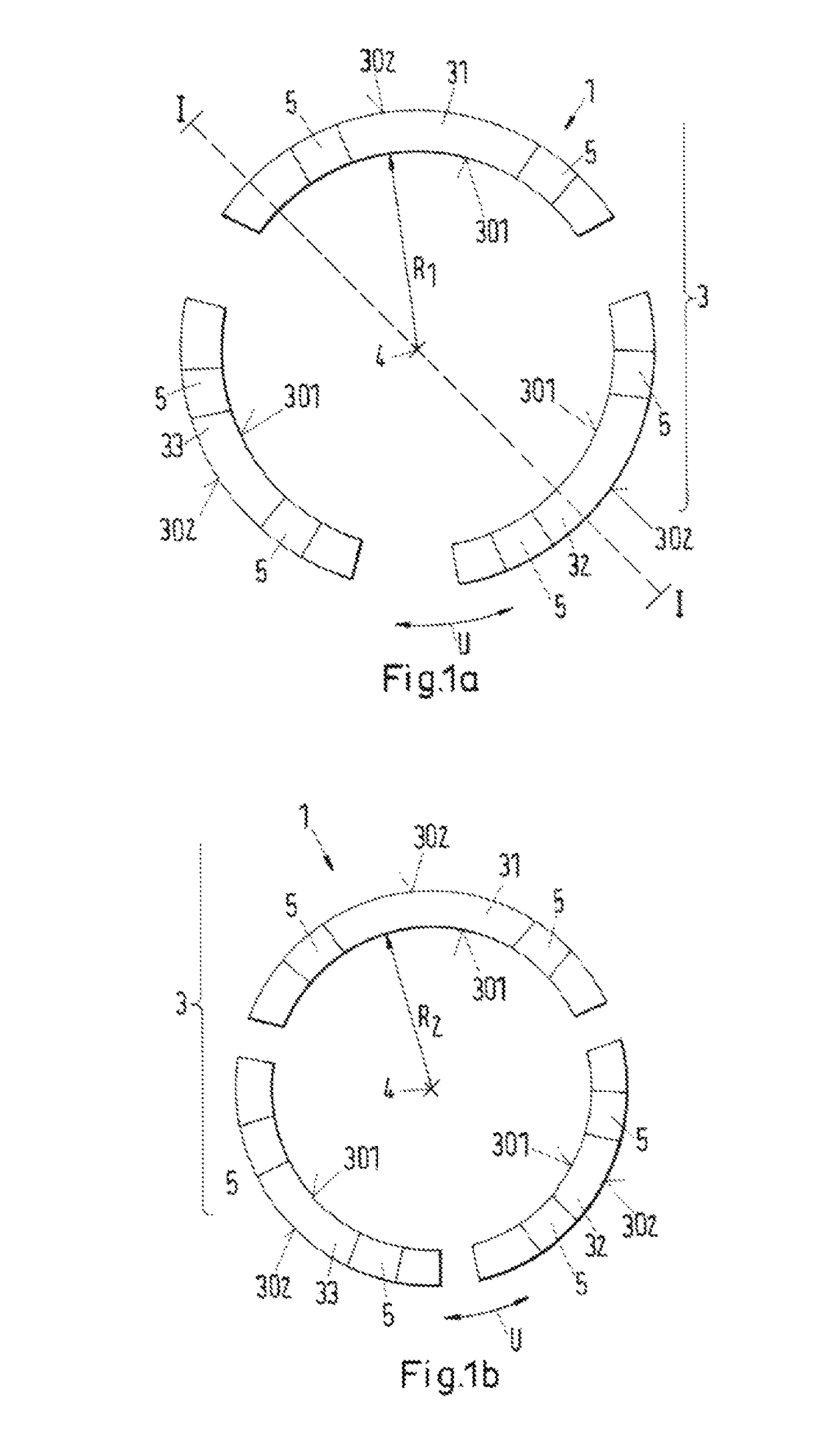
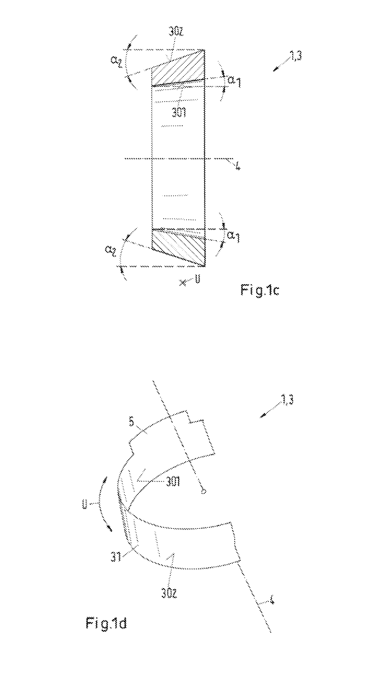
[0015]The present invention aims to avoid the disadvantages of what is known, in particular that is to provide a friction ring for a synchronization unit and a synchronizer ring such that an installation of the friction ring is simplified and such that an axial position of the friction ring and the synchronizer ring relative to one another can be set more reliably on installation and in operation and furthermore a high shifting comfort is enabled.

Problems solved by technology

In contrast, the self-locking effect, which prevents a release of the friction surfaces and substantially and noticeably impairs the shifting comfort for the driver, sets a natural limit to the minimization of the conical angle.
Nevertheless, they also increase the complexity, costs and not least, also the weight of the corresponding transmissions.
These already known friction rings can, however, be complex and / or expensive in handling under certain circumstances due to the segmentation if they are mounted at and / or in a synchronizing unit.
It can moreover occur that the friction ring and the synchronizer ring cannot be positioned sufficiently exactly with respect to one another in the axial direction or that a displacement in the axial direction takes place in operation.

Method used


Image

  • Friction ring, synchronizer ring, synchronizing unit as well as a variable gear transmission for a vehicle
  • Friction ring, synchronizer ring, synchronizing unit as well as a variable gear transmission for a vehicle
  • Friction ring, synchronizer ring, synchronizing unit as well as a variable gear transmission for a vehicle

Examples


Embodiment Construction

[0071]The particulars shown herein are by way of example and for purposes of illustrative discussion of the various embodiments of the present invention only and are presented in the cause of providing what is believed to be the most useful and readily understood description of the principles and conceptual aspects of the invention. In this regard, no attempt is made to show details of the invention in more detail than is necessary for a fundamental understanding of the invention, the description making apparent to those skilled in the art how the several forms of the invention may be embodied in practice.

[0072]The present invention will now be described by reference to more detailed embodiments. This invention may, however, be embodied in different forms and should not be construed as limited to the embodiments set forth herein. Rather, these embodiments are provided so that this disclosure will be thorough and complete, and will fully convey the scope of the invention to those ski...


PUM


Abstract

The invention relates to a friction ring (1) for a synchronizing unit (2) of a variable ratio gear transmission. The friction ring (1) comprises a conical friction body having an inner friction surface and an outer installation surface which each bound the friction ring body in a radial peripheral direction extending perpendicular to an axial friction ring axis (4). The friction ring body comprises a projection (9) for restraining a movement of the friction ring (1) relative to a synchronizer ring (7) substantially along the friction axis in operation in the synchronizing unit (2).

Description

[0001]The present application claims priority under 35 U.S.C. §119 of European Patent Application No. 13197885.0 filed on Dec. 17, 2013, the disclosure of which is expressly incorporated by reference herein in its entirety.CROSS-REFERENCE TO RELATED APPLICATIONS[0002]Not applicableSTATEMENT REGARDING FEDERALLY SPONSORED RESEARCH OR DEVELOPMENT[0003]Not applicableSTATEMENT REGARDING PRIOR DISCLOSURES BY THE INVENTOR OR A JOINT INVENTOR[0004]Not applicableBACKGROUND OF THE INVENTION[0005]The invention relates to a friction ring for a synchronizing unit of a selectable variable ratio gear transmission, to a synchronizer ring, to a synchronizing unit as well as to a variable ratio gear transmission for a vehicle in accordance with the preamble of the independent claims.[0006]In a mechanical, selectable variable ratio gear transmission, e.g. in vehicle transmissions, synchronizer rings serve to synchronize the relative speeds which occur between the gear wheel and the gear shaft on a gea...

Claims


Application Information

Patent Timeline
Patent Type & Authority Patents(United States)
IPC IPC(8): F16D23/06F16D23/02
CPCF16D23/025F16D23/06F16D2300/10F16H37/02F16H2306/48
Inventor SKIPPER, GARY I.SPRECKELS, MARCUSCHRISTOFFER, ULF
Owner OERLIKON FRICTION SYST GERMANY
Why Eureka
Try Eureka