Luminaire with a sensor that varies its activation in response to the presence or absence of objects

a technology of objects and sensors, applied in the field of luminaires, can solve the problems of greater number of lights that are deactivated, and achieve the effect of reducing power consumption and minimizing glar

Active Publication Date: 2015-12-22
KONINK PHILIPS ELECTRONICS NV
View PDF8 Cites 5 Cited by
  • Summary
  • Abstract
  • Description
  • Claims
  • Application Information

AI Technical Summary

Benefits of technology

[0008]In a preferred embodiment, the light source comprises a plurality of light emitting elements, the controller being configured to control at least some of said light emitting elements to modify the lighting parameter when the sensor detects movement of a person towards the light source. This is to prevent the vision of a person facing the light source from being impaired due to glare or excessive light being shined directly into their eyes.
[0009]The controller may be configured to modify the lighting parameter by deactivating some of said light emitting elements when the sensor detects movement of a person towards the light source. Deactivating some of the light emitting elements is a simple way of reducing the intensity of the light without having to control power levels.
[0010]The controller may be configured to change the number of light emitting elements that are deactivated in dependence on the distance of the person from the light source. Therefore, the number of lights that are deactivated can be greater when a person is closer to the light source, relative to when they are further away from it, and when the light emitted from the light source is more likely to cause irritation.
[0012]The controller may be configured to vary the power supplied to at least some of said light emitting elements in dependence on the distance of the person from the light source. Consequently, a greater power reduction may be employed when a person is closer to the light emitting elements so as to minimize glare.
[0013]Preferably, the luminaire includes a lens positioned in front of some of said light emitting elements to direct light emitted by said light emitting elements in a different direction to the direction in which light is directed by other light sources. This allows light to be directed in different directions, i.e. light that is directed through the lens may be focused in a particular direction.
[0015]Another embodiment comprises a reflector positioned to direct light emitted from said light emitting elements behind the lens in a direction towards said lens. The reflector prevents stray light from light emitted by the elements behind the lens from bypassing the lens.

Problems solved by technology

Therefore, the number of lights that are deactivated can be greater when a person is closer to the light source, relative to when they are further away from it, and when the light emitted from the light source is more likely to cause irritation.

Method used


Image

  • Luminaire with a sensor that varies its activation in response to the presence or absence of objects
  • Luminaire with a sensor that varies its activation in response to the presence or absence of objects
  • Luminaire with a sensor that varies its activation in response to the presence or absence of objects

Examples


Embodiment Construction

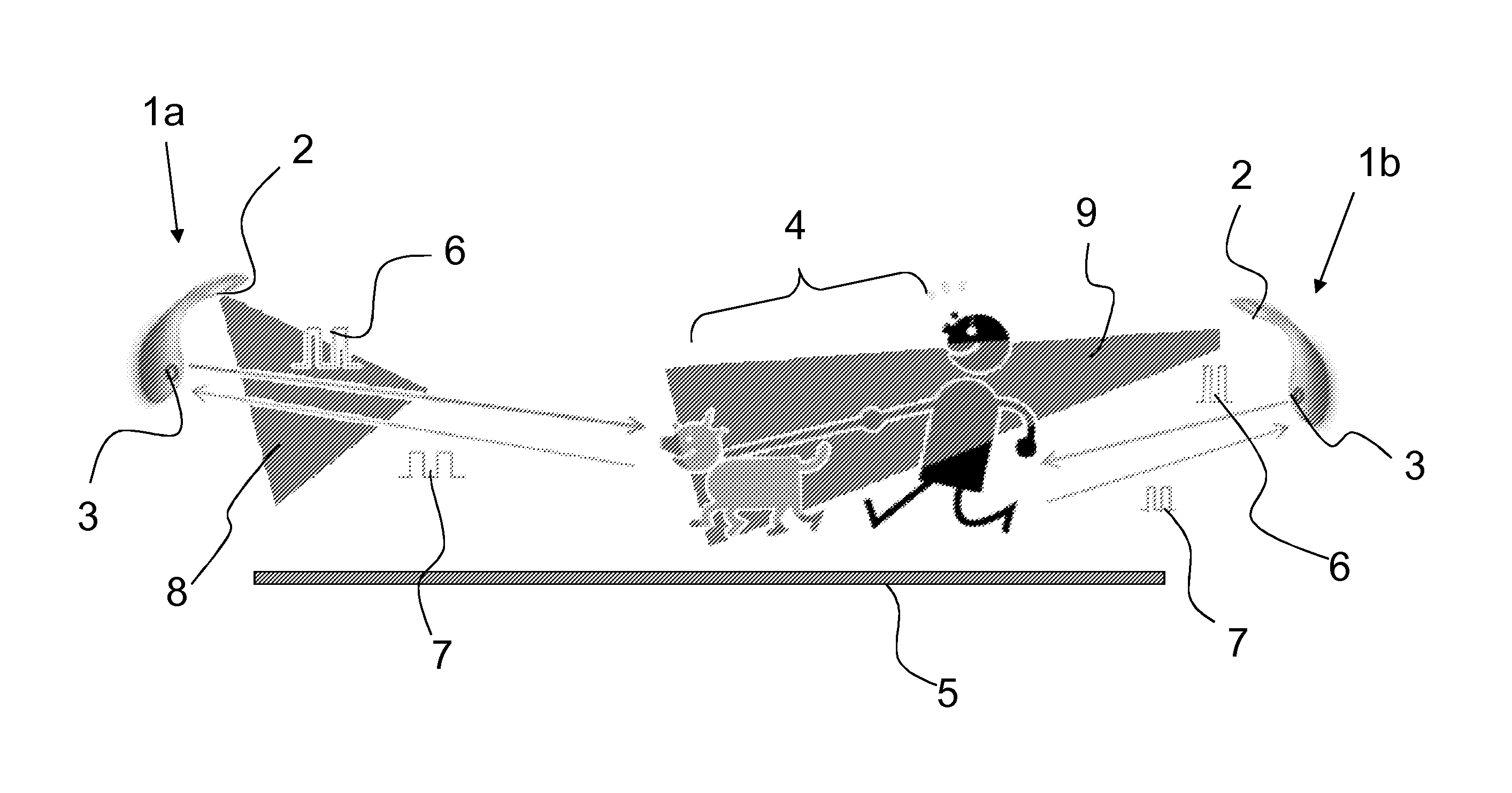
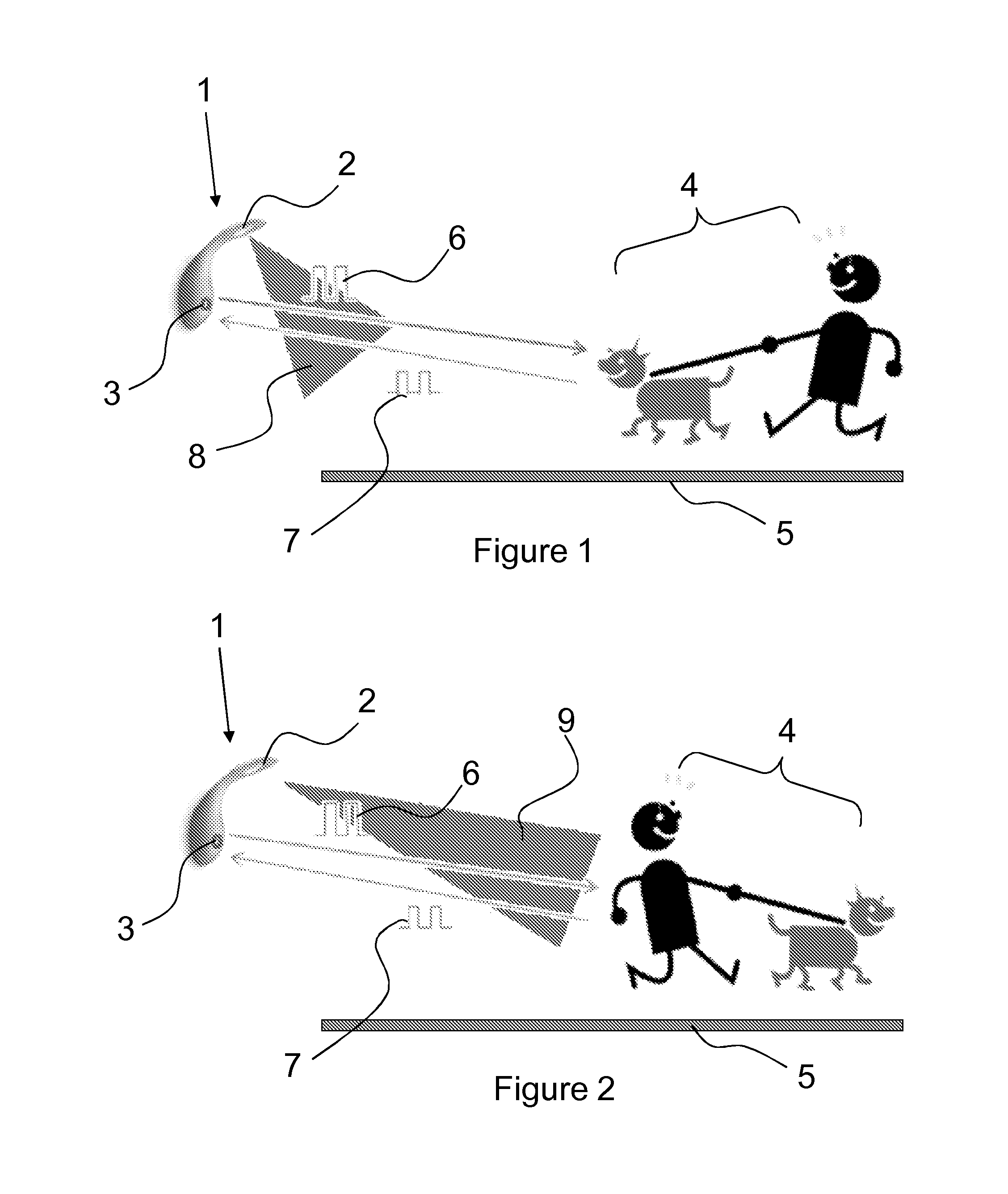
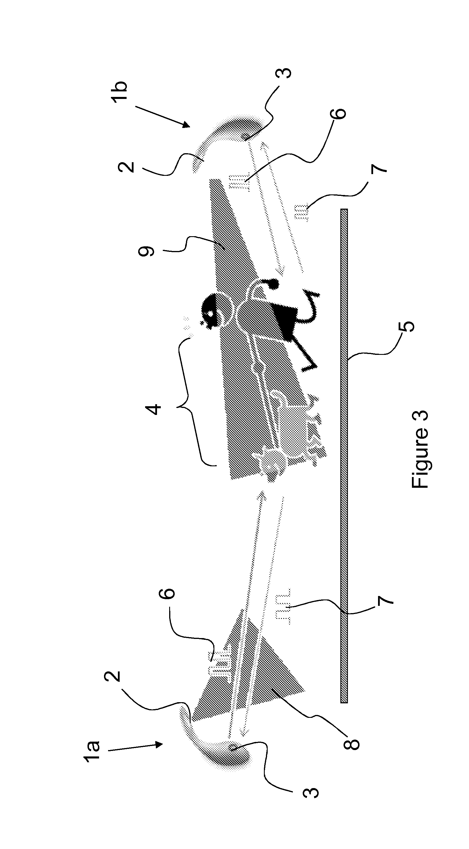
[0026]It is known in the art to use ultrasonic sensors to measure a distance; a piezoelectric transducer releases an ultrasonic wave pulse of a controlled duration and frequency and then a sensor will detect any echo waves that are returned. The transducer may be the sensor; however, if the transducer and sensor are separate components then they must be located proximate to each other in order to obtain accurate measurements. The echo waves are the ultrasonic waves emitted by the transducer that have been reflected back from any objects to the sensor. The sensor is configured to time the difference between the emission of the wave and detecting the echo wave. This time, combined with knowledge of the speed of the wave in air, allows the distance from the sensor to the object to be determined. A suitable ultrasonic wave pulse might be about 20 pulses at a frequency of 40 kHz. Ultrasonic sensors of this type are well known in the art and do not form a part of this invention. For this ...


PUM


Abstract

A luminaire (1a, 1b) and a method for controlling a luminaire are disclosed. The luminaire (1a, 1b) comprises a light source (2) and an ultrasonic sensor (3). The ultrasonic sensor (3) detects the presence and direction of movement of a person (4) with respect to the light source (2). A controller modifies a lighting parameter emitted from the light source (2) depending on whether a person (4) is moving towards or away from the light source (2).

Description

CROSS-REFERENCE TO PRIOR APPLICATIONS[0001]This application is the U.S. National Phase application under 35 U.S.C. §371 of International Application No. PCT / IB2012 / 056979, filed on Dec. 5, 2012, which claims the benefit of [e.g., U.S. Provisional Patent Application No. or European Patent Application No.] 61 / 568,193, filed on Dec. 8, 2011. These applications are hereby incorporated by reference herein.FIELD OF THE INVENTION[0002]This invention relates to a luminaire that activates in response to the presence of a person detected within a detection zone, such as a path or driveway.BACKGROUND OF THE INVENTION[0003]Wall mounted luminaires or lights for illuminating outdoor areas are often equipped with a motion detector that switches on a lamp when movement is detected. The detector is commonly an infrared sensor that detects infrared emissions radiated by a body, but they may also be ultrasound sensors that emit a high frequency wave pulse and listen to the echo to detect any physical ...

Claims


Application Information

Patent Timeline
Patent Type & Authority Patents(United States)
IPC IPC(8): H05B37/02H05B33/08H05B44/00
CPCH05B33/0854H05B37/0227Y02B20/44H05B47/115H05B45/10H05B47/10Y02B20/40
Inventor NEWTON, PHILIP STEVENKROON, BART
Owner KONINK PHILIPS ELECTRONICS NV
Why Eureka
Try Eureka