
Image projector and image projecting method

a projector and projector technology, applied in the field of image projector and image projecting method, can solve the problems of complicated configuration of the apparatus, interference with the size of the apparatus, and the problems of causing problems with the conventional apparatus, so as to reduce the intensity of light, and reduce the effect of light intensity

Inactive Publication Date: 2005-06-16
SONY CORP
View PDF7 Cites 54 Cited by
  • Summary
  • Abstract
  • Description
  • Claims
  • Application Information

AI Technical Summary

Benefits of technology

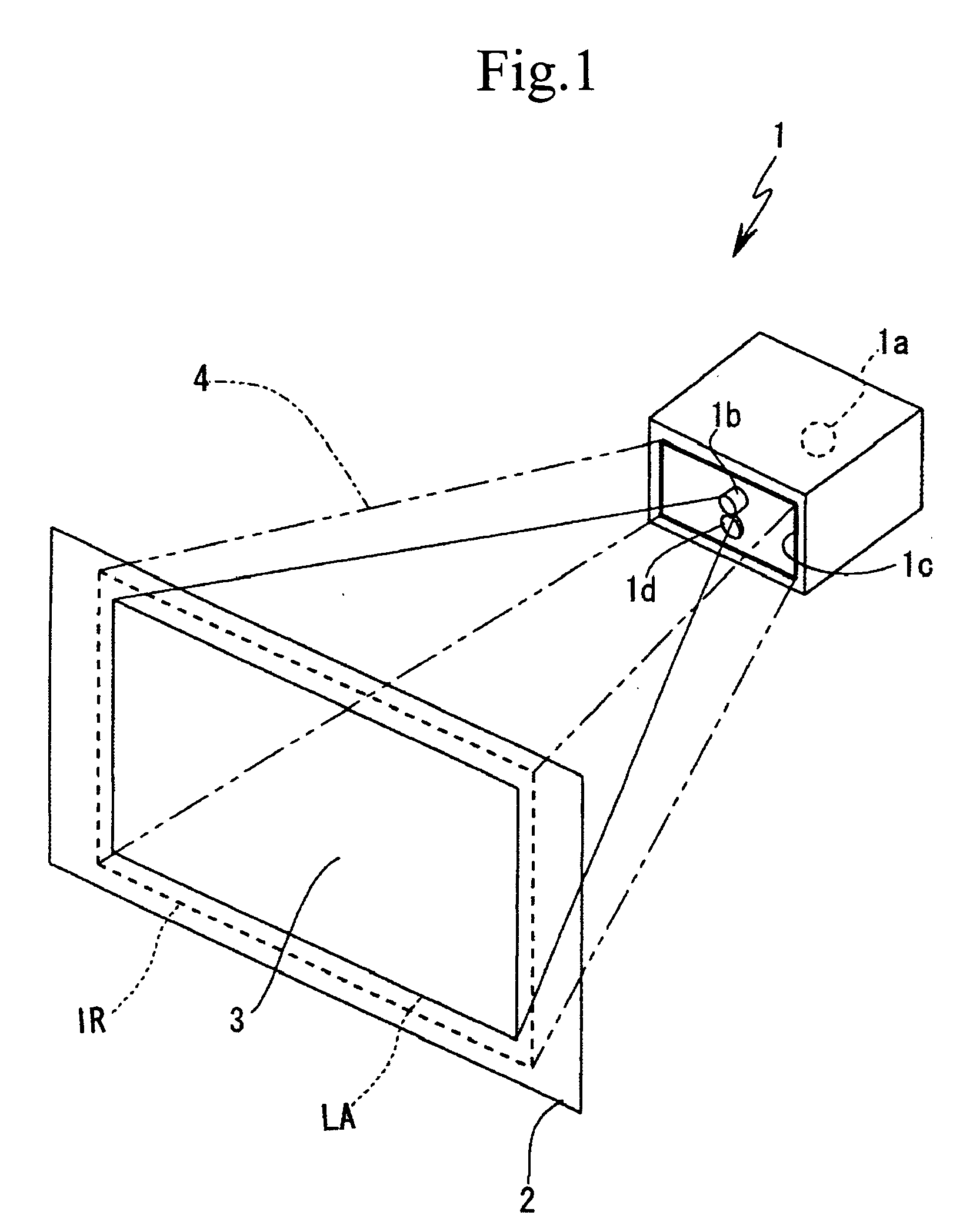
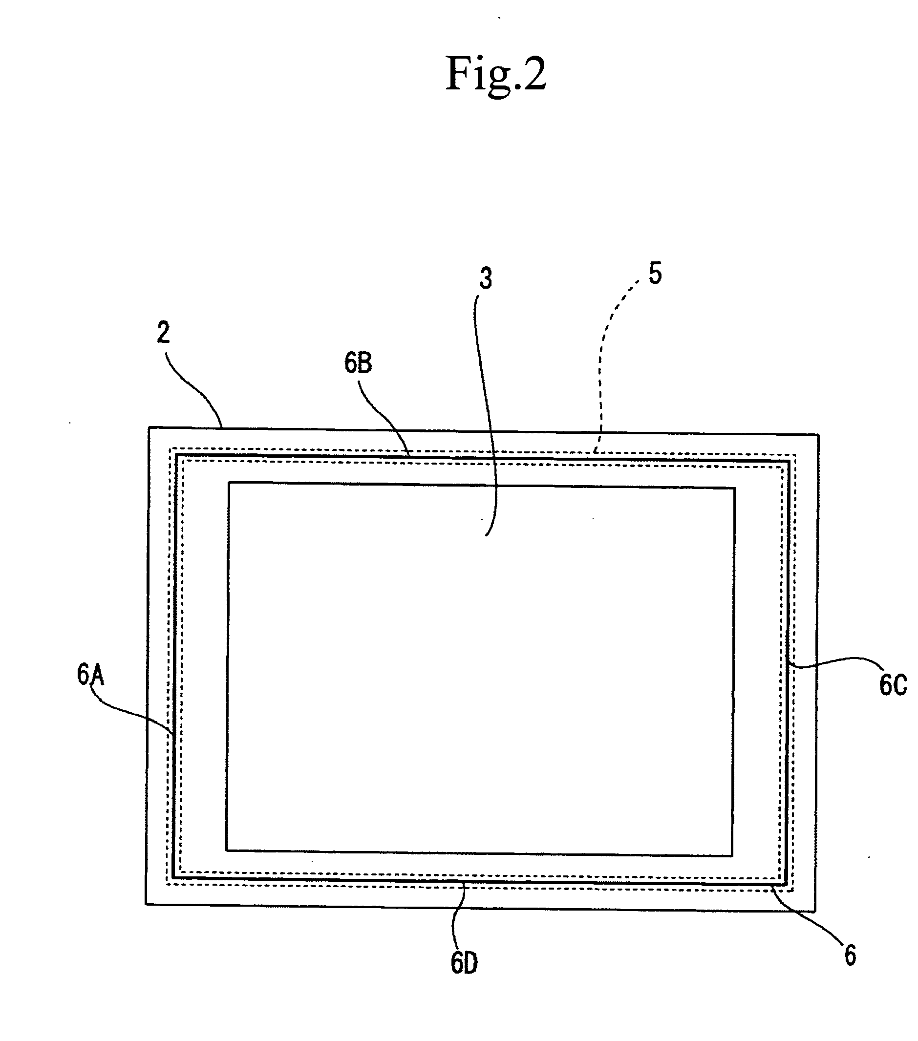
[0009] Moreover, an image projection method according to the present invention regulates a monitoring area located on an outside of a projection area on a screen apart from the projection area, the screen located at a distance from an image projection apparatus, and emits a detection wave from a detection wave source provided on a front surface of the image projection apparatus toward the monitoring area, and further detects entry into a monitoring space surrounded by the detection wave by detecting a reflection wave from the monitoring area, and thereby cut offs light radiated toward the projection area or reduces intensity of the light according to an entry state.
[0010] Consequently, according to these inventions, a detection wave source opposed to a screen is provided, and a reflection wave emitted from the detection wave source and reflected from a monitoring area is detected. Accordingly, entry into a monitoring space can be detected with a simple configuration. Then, when the entry into the monitoring space is detected, it is possible to prevent the human body from being exposed to danger by cutting off a radiation light to a projection area or by reducing light intensity.

Problems solved by technology

That is, a danger in the case where a laser light directly entered the eye is pointed out.
Now, the conventional apparatus have the problems caused by taking such a safety measure.
The problems are, for example, that the configuration of an apparatus becomes complicated; that such a measure interferes with making the size of an apparatus larger; and the like.
However, when the attachment of the safety mechanism brings about disadvantages such as the growth of the complexity of a projection optical system and the like, a remarkable rise of an apparatus cost, and the like, it is apprehended that the disadvantages cause a hindrance of diffusion and the like.

Method used


Image

  • Image projector and image projecting method
  • Image projector and image projecting method
  • Image projector and image projecting method

Examples


Embodiment Construction

[0031] The present invention aims to secure safety by immediately cutting off light or reducing light intensity when an obstacle enters the projection area of a radiation light (such as a laser light or the like) in an image projection apparatus.

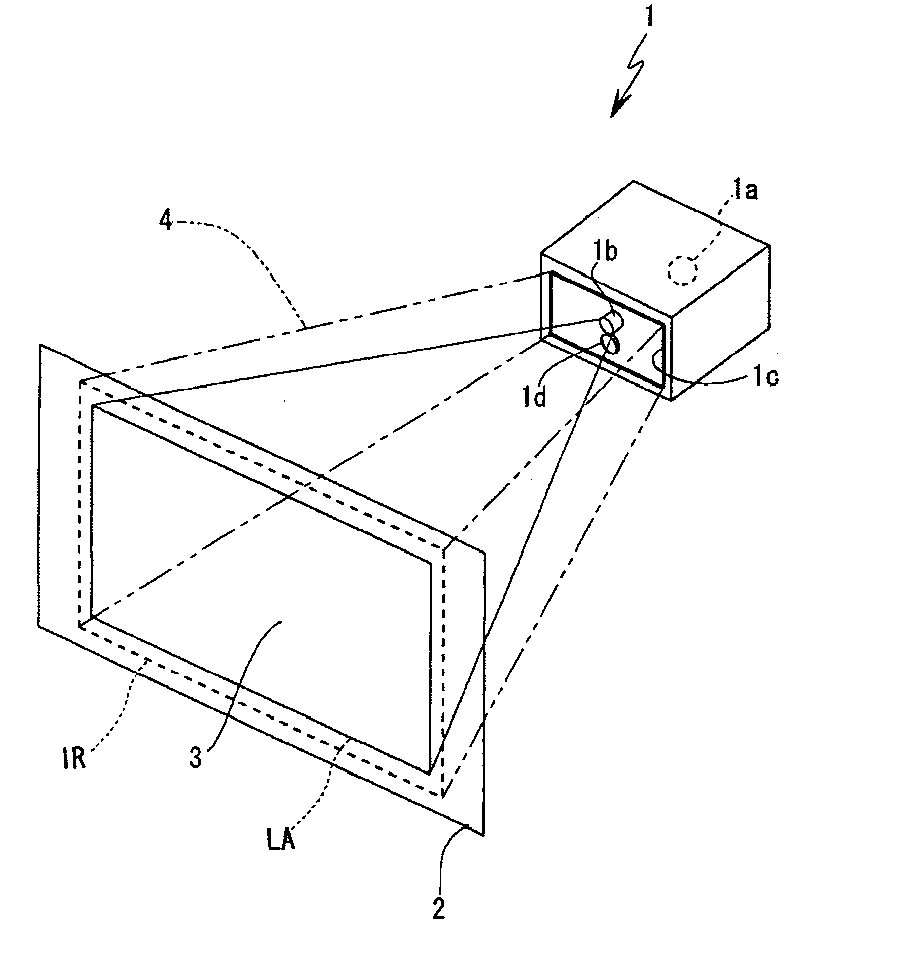
[0032]FIG. 1 schematically shows a basic configuration example of an image projection apparatus according to the present invention, and shows an example of an apparatus using a laser light source (a laser projector apparatus and the like).

[0033] An image projection apparatus 1 includes a light source 1a for performing image display by projection to a projection area 3 on a screen 2 located at a fixed distance from an apparatus main body unit, and a projection unit 1b including a projection lens. For example, a configuration which is provided with laser light sources (the laser light source of each color of R, G and B) and an optical modulator (modulation means) and includes the function of projecting an image on the screen 2 by the use of ...


PUM


Abstract

In an image projection on a screen, an image projection apparatus improves the safety of entry into a projection region by the human body and does not bring about the increase of complexity of the configuration thereof owing to the improvement of the safety. A monitoring area is regulated on the outside of the projection area (3) of the screen (2). A detection wave such as infrared rays is emitted from a detection wave source (1c) of the image projection apparatus (1). A reflection wave from the monitoring area is detected by reflection wave detection means (1d) such as a CCD sensor. Whether the human body or an obstacle enters the monitoring space, which is surrounded by a detection wave (4) between the main body unit of the image projection apparatus (1) and the screen (2), or not is detected. Once the entry is detected, the intensity of the radiation light traveling toward the projection area (3) is reduced or cut off according to the situation or the degree of the entry.

Description

TECHNICAL FIELD [0001] The present invention relates to a technique for taking a sufficient safety measure in an image projection apparatus and an image projection method which are constituted by using a high intensity light source. BACKGROUND ART [0002] As an image display apparatus capable of large screen display, a projection type projector apparatus is known. A viewer can view a projected image by projecting light from a light source onto a screen. [0003] As a light source of a projector apparatus, a high luminance projection tube has been used until now. However, with the object of the improvement of brightness, color reproducibility and the like, the object of the easiness of modulation by an image signal, and the other objects, a projection system using the laser light sources of red (R), green (G) and blue (B) has been proposed. [0004] In the mean time, when a laser light is used, the securement of the safety thereof is an important task. For example, it is needed to take an...

Claims


Application Information

Patent Timeline
Patent Type & Authority Applications(United States)
IPC IPC(8): G03B21/00G08B21/02H04N5/57H04N5/74H04N9/31H04N17/00H04N17/04
CPCG03B21/00H04N5/57H04N9/3179H04N9/3129H04N5/74G03B21/2086G03B21/005G03B21/14
Inventor SUGAWARA, YUTAKAEGUCHI, NAOYA
Owner SONY CORP
Learn More