Distributed Optical Fibre Sensing

a technology of optical fibre sensing and distributed optical fiber, applied in the direction of optical radiation measurement, instruments, spectrometry/spectrophotometry/monochromators, etc., can solve problems such as connector damag

Active Publication Date: 2012-05-24
VIAVI SOLUTIONS INC
View PDF3 Cites 57 Cited by
  • Summary
  • Abstract
  • Description
  • Claims
  • Application Information

AI Technical Summary

Benefits of technology

[0034]The invention also provides methods, and corresponding apparatus, for distributed vibration sensing using Rayleigh backscatter within a multiple mode optical fibre, comprising coupling an interrogator to the multiple mode optical fibre using a double clad optical fibre having a single mode waveguide and a multiple mode waveguide, receiving at the interrogator, through the single mode waveguide of the double clad optical fibre, light backscattered within the multiple mode op

Problems solved by technology

If high probe light powers are required for a sensing operation using a single mode waveguide, then su

Method used


Image

  • Distributed Optical Fibre Sensing
  • Distributed Optical Fibre Sensing
  • Distributed Optical Fibre Sensing

Examples


Embodiment Construction

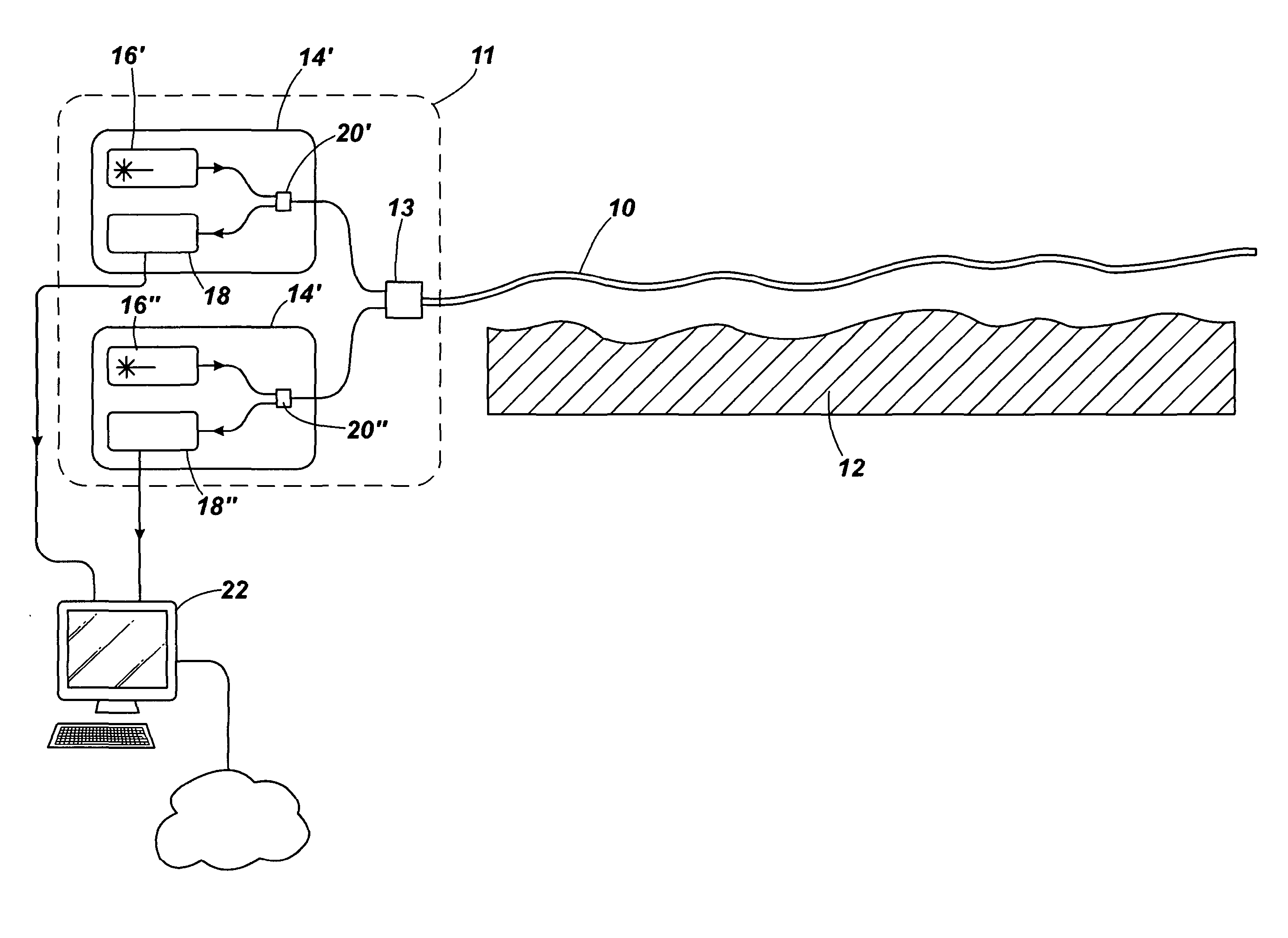
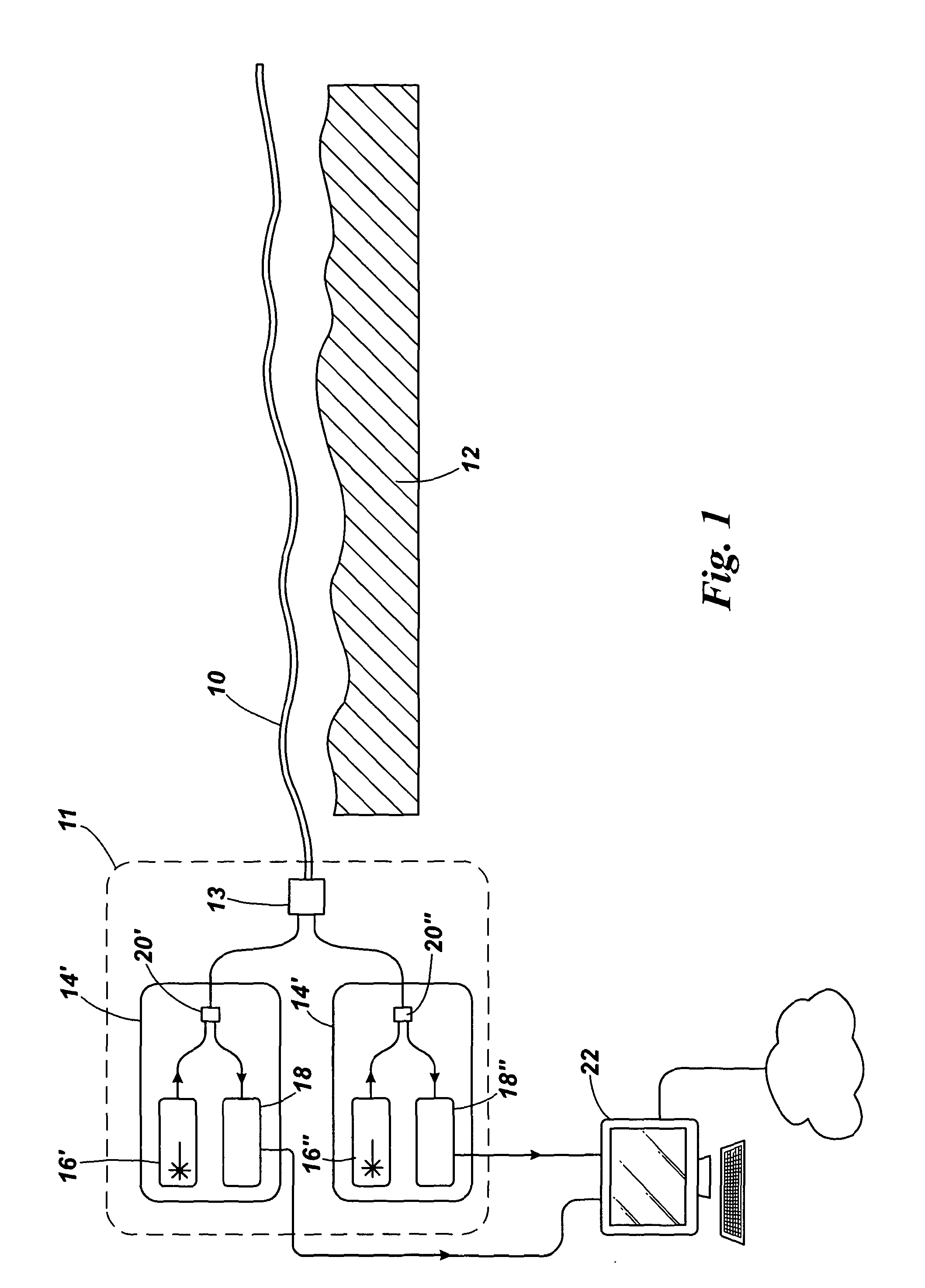
[0042]Referring to FIG. 1 there is shown an example distributed optical sensing system according to the invention. A sensor fibre 10, which may be housed for example as part of a cable structure, extends through an environment to be monitored, for example along a structure 12 such as a pipeline. The sensor fibre is a double clad optical fibre, although other fibre types having two or more waveguides extending together along the fibre may be used. The sensor fibre 10 is coupled to an interrogator system 11. In FIG. 1 the interrogator system comprises two interrogator units 14′ and 14″, which are both coupled to the sensor fibre using a combiner 13. Each interrogator unit 14 includes a probe light source 16, an optical analyser 18, and a coupler 20 to link both the respective probe light source 16 and the respective optical analyser 18 to a fibre running to the combiner 13. Typically, each probe light source 16 might include a laser such as a semiconductor laser, driving electronics f...


PUM


Abstract

There is disclosed a distributed optical fibre sensing system in which the sensor fibre comprises at least first and second waveguides used for separate sensing operations. The sensor fibre may be, for example, a double clad fibre having a monomode core and a multimode inner cladding.

Description

[0001]The present invention relates to apparatus and methods for distributed optical sensing, in which parameters such as temperature, strain and vibration are measured along extended lengths of a sensor optical fibre, as a function of position along the sensor fibre, by detecting properties of light scattered within the fibre.INTRODUCTION[0002]Distributed optical fibre sensing is a well known approach to providing information about environmental conditions along the length of a sensor optical fibre which can extend for considerable distances along structures such as pipelines, cables, buildings and bridges, down boreholes, and in numerous other applications. In principle, spatially resolved information about environmental conditions can be obtained from every point along the sensor fibre, subject to issues such as spatial resolution, and reduced signal strength as the range is extended. Environmental parameters that can be sensed through their corresponding influence on the optical...

Claims


Application Information

Patent Timeline
IPC IPC(8): G01D5/353G01J3/44
CPCG01D5/353G01D5/35364G01J3/44G01V1/40G01V1/226G01D5/35361
Inventor HANDEREK, VINCENT ANDREI
Owner VIAVI SOLUTIONS INC
Why Eureka
Try Eureka