Emergency stop device for a rotary platform of a milking parlour

a technology of a rotary platform and a stop device, which is applied in the direction of milking devices, mechanical devices, animal husbandry, etc., can solve the problem of not being able to reach the upper part of the obj

Inactive Publication Date: 2015-12-29
DELAVAL HLDG AB
View PDF17 Cites 1 Cited by
  • Summary
  • Abstract
  • Description
  • Claims
  • Application Information

AI Technical Summary

Benefits of technology

[0004]The object of the present invention is to achieve an emergency stop device for a rotary platform ensuring that an operator who gets stuck in the platform or a part of it will not be squeezed between the platform and a component arranged beside the platform.
[0005]This object is achieved by the emergency stop device initially defined, which is characterised in that the detecting area is located beside the edge portion of the platform at an upstream distance from said component with reference to the rotary direction of the platform, wherein said upstream distance is longer than an estimated stopping distance of said edge portion when the platform is emergency stopped. In case an object such as an operator gets stuck in the platform, this will be detected by the detecting means when the operator has been dragged to the detecting area. When this happens, the detecting means initiates an emergency stop of the platform. Since the detecting area is located at a longer distance from the component than the estimated stopping distance of said edge portion of the platform, the platform will be stopped before the operator reaches the component. Thereby, the risk that the operator is squeezed between the platform and the component is eliminated. The emergency stopping distance of a platform may be for example 5 to 10 cm at an edge portion of the platform. The detecting means may in this case be arranged at a distance of, for example, 10 to 50 cm from the component. Preferably, the detecting area is arranged relatively close to the component such that there is no risk that an operator gets stuck in the platform in a position between the detecting area and the component. The detecting means may, for example, comprise a vertical light beam or the like which is broken when an object reaches the detecting area.
[0008]According to a preferred embodiment of the invention, the emergency stop device comprises a stationary unit and supporting means allowing a movable support of the movable unit on the stationary unit. The contact surface of the movable unit is here located at a distance from the stationary unit such that the movable unit is able to perform the motion from the first position to the second position. The supporting means may comprise at least one rolling member and a rail member arranged in contact with said at least one rolling member. Such supporting means allows a well defined displacement path for the movable unit in relation to the stationary unit when it is displaced from the first position to the second position.
[0012]According to an embodiment of the invention, the movable unit comprises an outer casing which substantially encloses the stationary unit. Such an outer casing may form the whole outer surface of the post element. Thereby, the risk is eliminated that an object dragged by the platform comes in direct contact with the stationary unit. Thus, there is no possibility for the object to move past the contact surface of the movable unit and come in contact with the stationary post element. Furthermore, such a casing provides a protection for the resilient means and the supporting means arranged between the movable unit and the stationary unit.

Problems solved by technology

Thereby, it is not possible for an upper part of the object to pass above the detecting area and be squeezed between the platform and the component.

Method used


Image

  • Emergency stop device for a rotary platform of a milking parlour
  • Emergency stop device for a rotary platform of a milking parlour
  • Emergency stop device for a rotary platform of a milking parlour

Examples


Embodiment Construction

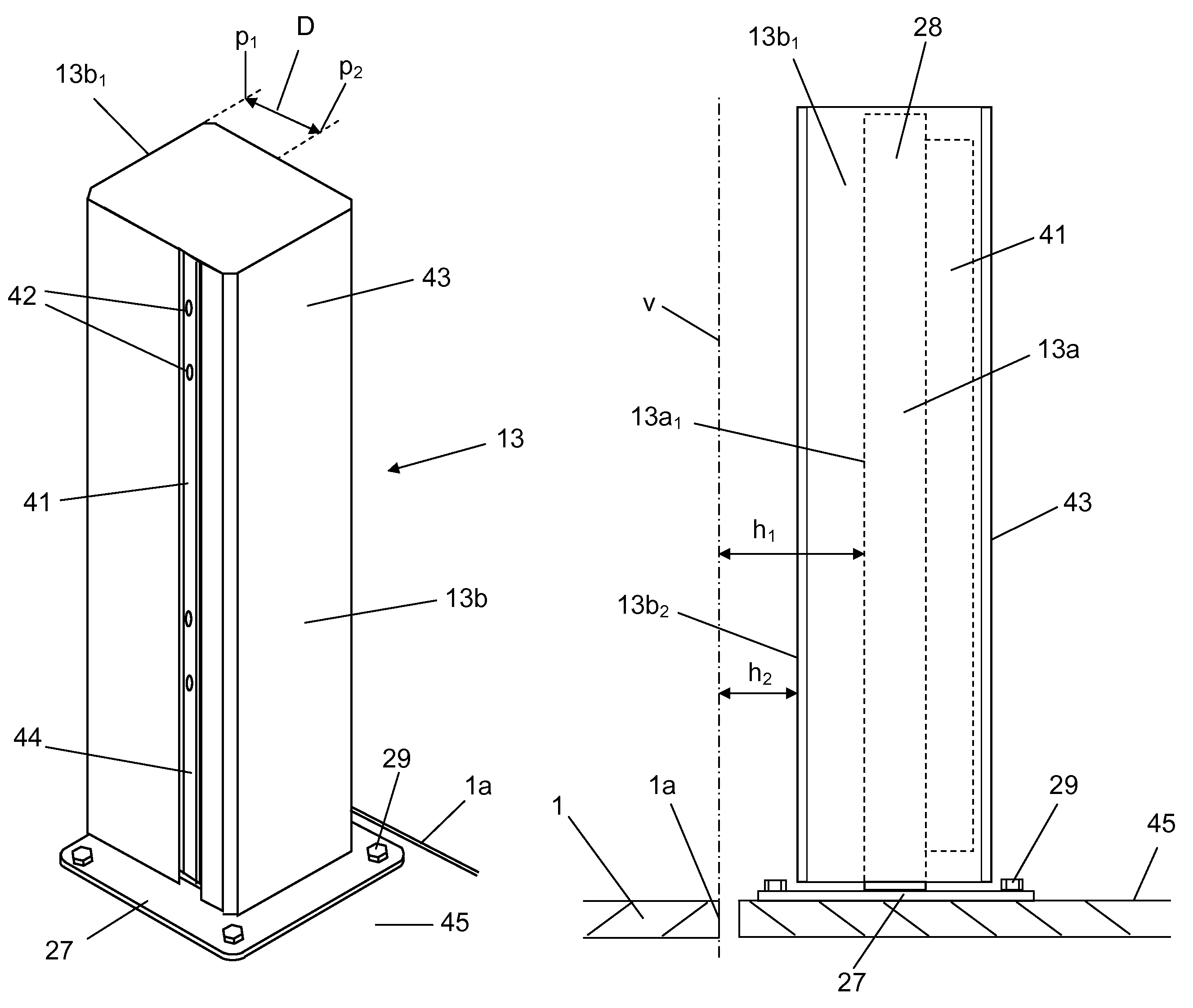
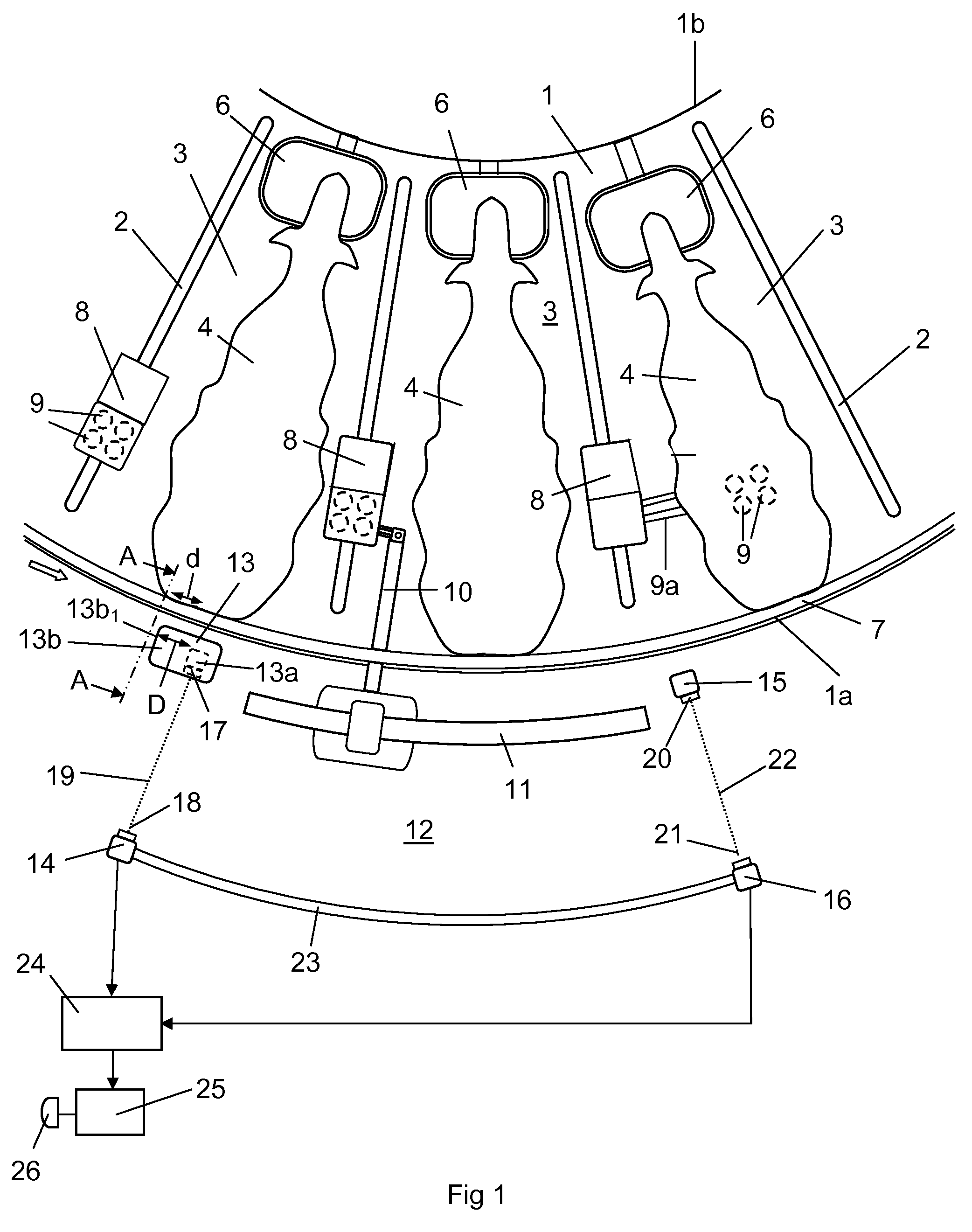
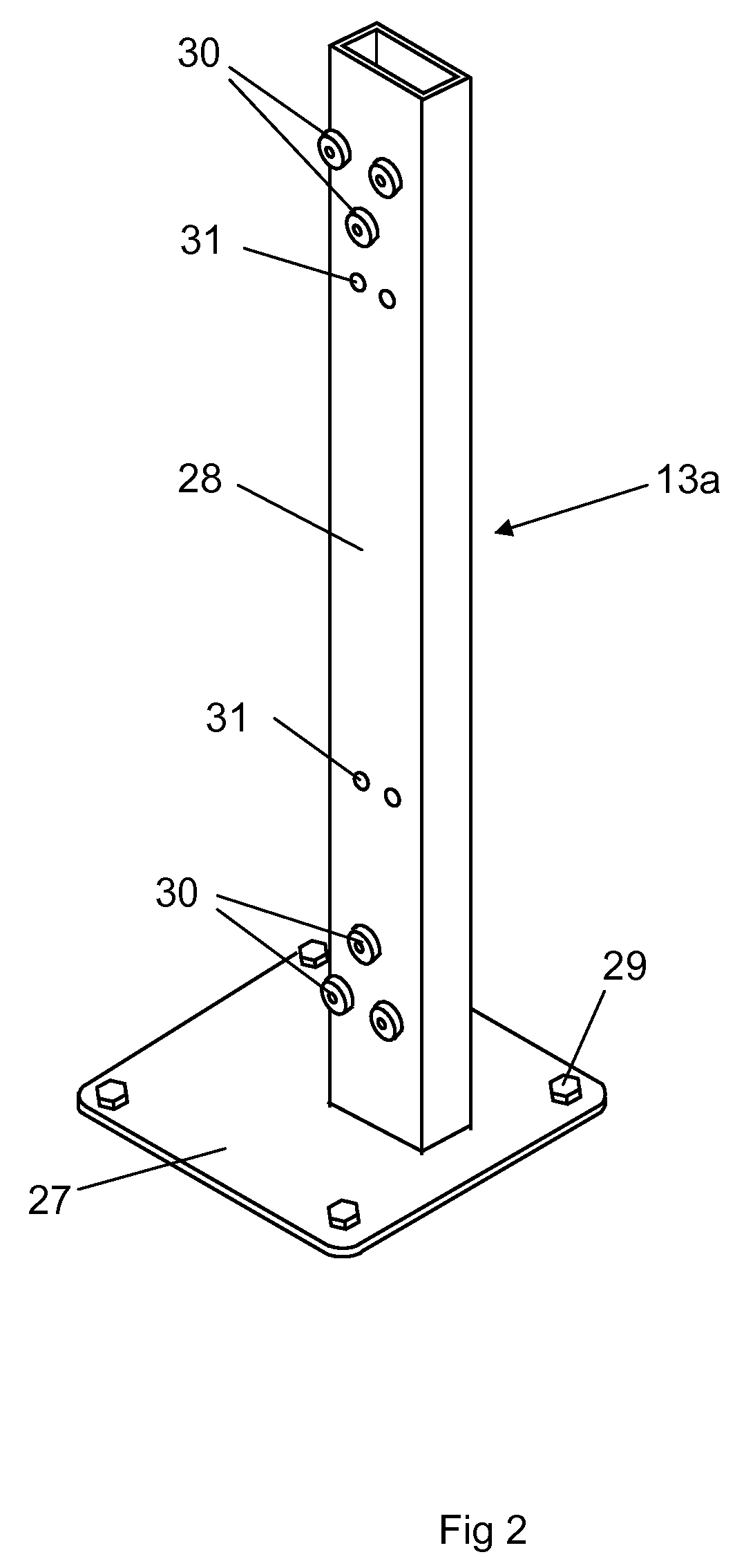
[0018]FIG. 1 shows a part of an annular rotary platform 1. The annular platform is defined by an outer radial edge portion 1a and a radial inner edge portion 1b. The platform 1 is provided with a plurality of side wall elements 2 each having a substantially radial extension on the platform 1. The side wall elements 2 divide the annular platform into a plurality of milking stalls 3. FIG. 1 shows three of the milking stalls 3 on the rotary platform 1. Each milking stall 3 contains a milking cow 4. The cows 4 are here positioned in a substantially radial direction on the annular platform 1 with the heads in the vicinity of the inner edge portion 1b of the platform 1.

[0019]Each milking stall 3 comprises a feeding trough 6. A rump rail 7 is arranged at a distance above a radial outer edge portion 1a of the platform 1. The rump rail 7 is adapted to define the positions of the rear portions of the cows 4 in the milking stalls 3. Each milking stall 3 comprises a teat cup storing device 8 ad...


PUM


Abstract

An emergency stop device for a rotary platform (1) of milking parlor for a milking parlor that includes at least one component (10, 13a) arranged beside an edge portion (1a, 1b) of the platform (1). The emergency stop device includes a detecting element (13b) adapted to initiate an emergency stop of the rotary platform (1) in a case of an object being detected in a detecting area (13b1) located beside the edge portion (1a, 1b) of the platform (1) at an upstream distance (D) from the component (10, 13a) with respect to the rotary direction of the platform (1). The upstream distance (D) is longer than an estimated stopping distance (d) of the edge portion (1b) when the platform (1) is emergency stopped.

Description

THE BACKGROUND OF THE INVENTION AND PRIOR ART[0001]The present invention relates to an emergency stop device for a rotary platform in a milking parlour, wherein the milking parlour comprises at least one component arranged beside an edge portion of the platform and wherein the emergency stop device comprises detecting means adapted to initiate an emergency stop of the rotary platform in case an object is detected in a detecting area.[0002]In a conventional parallel rotary parlour, the cows walk onto an annular rotating platform and enter a milking stall. An operator or a milking robot located on the outside or on the inside of the annular platform, attaches teat cups to the teats of the cows. The platform may rotate continuously with a constant low speed. The milking process for a cow has finished when the cow has rotated nearly 360 degrees on the platform. The continuous flow of cows make rotary parlours have a high milking capacity.[0003]There is a risk that operators working in t...

Claims


Application Information

Patent Timeline
Patent Type & Authority Patents(United States)
IPC IPC(8): A01J5/00A01K1/12F16D63/00
CPCA01K1/126F16D63/00
Inventor OBERMULLER, HELMUT
Owner DELAVAL HLDG AB
Why Eureka
Try Eureka