External structural brace apparatus

a brace and external technology, applied in the field of external structural exoskeleton apparatus, can solve the problems of increasing the force load on the user's back, leaving the user worse off, and the inability of the kelly to adjust the amount of support offered by the apparatus, so as to increase the speed of retraction movement

Active Publication Date: 2016-01-05
THRELFALL JOHN
View PDF38 Cites 5 Cited by
  • Summary
  • Abstract
  • Description
  • Claims
  • Application Information

AI Technical Summary

Benefits of technology

[0025]Continuing, the external structural brace apparatus includes a third means for facilitating same direction movement of the third handle structure and the first telescoping cantilever beam, wherein there is a decreasing speed of relative movement of the first telescoping cantilever beam in relation to the third handle structure movement, as the third handle structure is manually pushed toward the first telescoping cantilever beam, to accommodate the user being able to more precisely position the first telescoping cantilever beam on the surface as the user's arm is extended toward the first telescoping cantilever beam. Further the third means accommodates an increasing speed of retraction movement of the first telescoping cantilever beam as the third handle structure is manually pulled away from the first telescoping cantilever beam to help the first telescoping cantilever beam better clear obstacles on the surface for the user to ambulate along the surface.
[0026]Further, the external structural brace apparatus includes a fourth means for facilitating same direction movement of the fourth handle structure and the second telescoping cantilever beam, wherein there is a decreasing speed of relative movement of the second telescoping cantilever beam in relation to the fourth handle structure movement, as the fourth handle structure is manually pushed toward the second telescoping cantilever beam, to accommodate the user being able to more precisely position the second telescoping cantilever beam on the surface as the user's arm is extended toward the second telescoping cantilever beam. Further the third means accommodates an increasing speed of retraction movement of the second telescoping cantilever beam as the fourth handle structure is manually pulled away from the second telescoping cantilever beam to help the second telescoping cantilever beam better clear obstacles on the surface for the user to ambulate along the surface.

Problems solved by technology

Two major problems with Mendenhall are that it requires additional effort from the user to do the initial bending or stooping over as the wires 16 will limit the amount of bending over that can be done, and further to this the wire 16 with the attachment point on the user's shoulders and upper legs acts to put the user's back into added compression, thus the exoskeleton in Mendenhall does not itself carry any of the user's load, it simply transfers the load to the added compressive force upon the user's back, which is undesirable.
However, much the same as Mendenhall, the coiled springs put compressive stress upon the back of the user which is undesirable and the exoskeleton carries absolutely no weight or load itself, as the flexible straps and coiled springs apparatus of Vigne has no independent stiffness of its own and thus does not remove any load from the user's bone structure and even worse both Mendenhall and Vigne further increase the compressive force loading on the user's back, thus in effect leaving the user worse off than if they did not use the Mendenhall or Vigne apparatus at all.
In addition, Kelly does not offer a means to adjust the amount of support offered by the apparatus.
However, Kelly still has a component of longitudinally based tensile contracting force due to the coil spring, and thus can still put the user's back in undesirable compression, thus having the same drawbacks as Mendenhall and Vigne in that area as previously described.
The Williamson apparatus provides unbalanced asymmetrical support to the back by strapping itself to only one leg of an individual, as the asymmetrical attachment to the individual creates unequal support for the left and right lower back.
Finally, the next reference to Naig in U.S. Pat. No. 3,570,011 does a better job of not compressing the user's back by using a beam 12 that pivots upon the user's lower back to simply pull against the user's upper chest in a manner completely perpendicular to the user's back, however, adding the somewhat undesirable issue of putting the user's lower back and legs into compression, which probably being better than putting the user's back into compression via elastic straps 52, whereas straps 44 are not stretchable, thus even this compression is still not desirable, further Naig is quite large and bulky, especially due to tubular frame 12, see in particular FIG. 2.
The Deamer apparatus only provides one way support and restraint to the lower back when an individual bends forward and does not provide support for bending backward.
Taylor requires the individual to install and wear a cumbersome number of straps buckled to the torso, shoulders, upper back, mid torso, upper legs, mid-legs, ankles and feet.
Continuing in this area in the prior art in the U.S. Pat. No. 6,450,131 to Broman which is similar to Mendenhall discloses a light flimsy harness for supposedly preventing lower back injuries caused by improper bending and lifting however, again as in Mendenhall, the user's back is put undesirably into compression from the user bending over or stooping and also as in Mendenhall the Broman apparatus has no independent stiffness with which to support any weight or load.

Method used


Image

  • External structural brace apparatus
  • External structural brace apparatus
  • External structural brace apparatus

Examples


Embodiment Construction

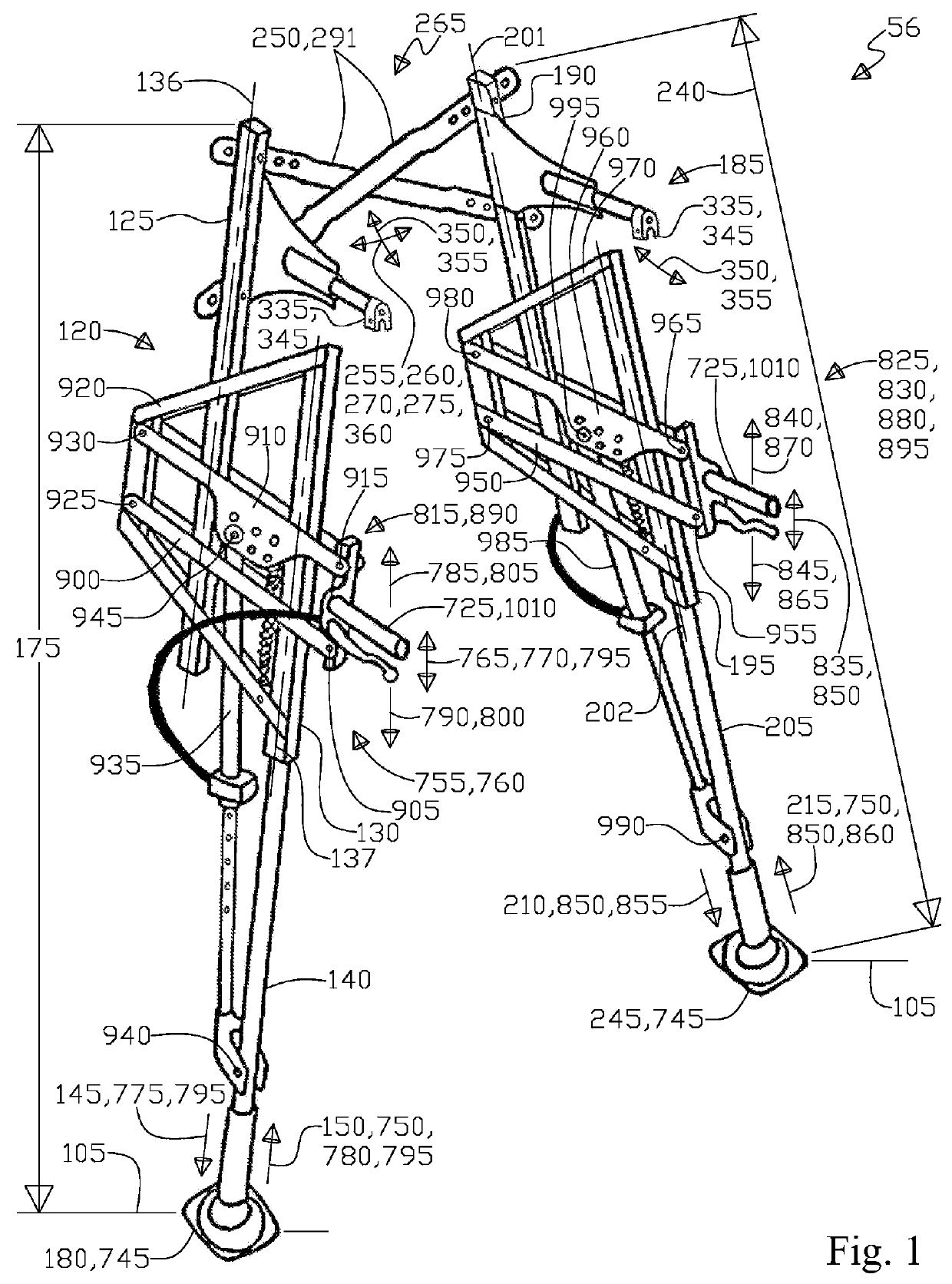
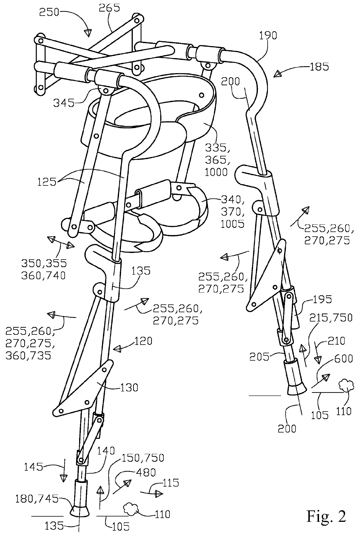
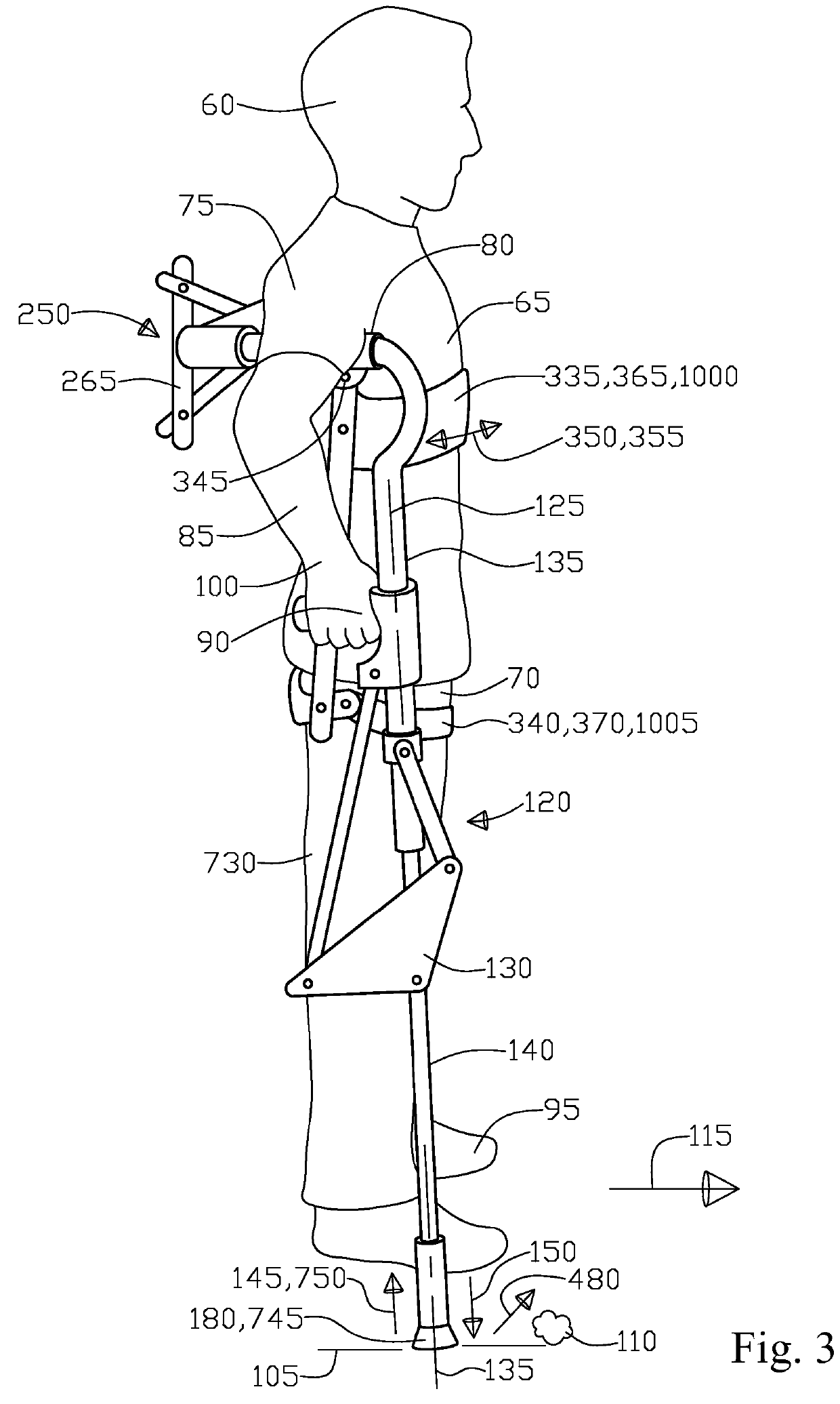
[0243]With initial reference to FIG. 1 shows a perspective view of a substitute structural brace apparatus 56. Next, FIG. 2 shows a perspective view of a crutch apparatus noting in particular the attachment element 335 with the user 60 upper torso 65 removable engagement 365 and the user 60 hip portion 70 removable engagement 340 along with the secondary pivotal movement 350 and plane 355, plus a mechanism 265, a primary pivotal couple 250, primary pivotal movement 255 and plane 260. Next, FIG. 3 shows a side elevation view of the crutch apparatus in use with a user 60 noting in particular the attachment element 335 that is engaged with the user 60 upper torso 65 removable engagement 365 and the user 60 hip portion 70 that is engaged 340 with the attachment element 335 removable hip portion engagement 340 along with the attachment element 335 secondary pivotal movement 350 and plane 355, plus a mechanism 265, a primary pivotal couple 250, primary pivotal movement 255 and plane 260.

[...


PUM


Abstract

An external structural brace apparatus and method for supporting a user on a surface and for the user to ambulate along the surface to relieve shoulder, armpit, hand, foot, and wrist loads, the apparatus includes first and second support beams that each have a telescoping cantilever beam that contacts the surface. The first and second support beams have a primary pivotal couple at one end to one another with a mechanism to create opposite symmetrical movement of the beams. An attachment element supports the user at their torso has a secondary pivotal connection to the first and second beams and third and fourth user handles that are pivotally attached to the first and second beams are for grasping by the user to extend and retract the telescoping cantilever beams to and from the surface at reduced and increased extension and retraction rates for user ease of ambulating along the surface.

Description

RELATED APPLICATIONS[0001]There are no related applications claiming priority.TECHNICAL FIELD OF INVENTION[0002]The present invention generally relates to a portable external structural exoskeleton apparatus utilized typically by an article for bracing and strengthening of the article. More particularly, the present invention helps maintain the structural relationship and integrity between the upper, middle, or lower body structures, in addition to restricting over extension of these body structures in an effort to minimize stress and potential injury to the individual's torso and limbs. Further, more particularly, the present invention provides an active, portable, and lightweight exoskeleton support apparatus that can be worn for long periods of time to assist an individual in performing repetitive high load movements involving stress to the structural portion of an individual's torso and limbs for activities that can include bending, lifting, and standing for extended periods of ...

Claims


Application Information

Patent Timeline
Patent Type & Authority Patents(United States)
IPC IPC(8): A61H3/02
CPCA61H3/02A61H3/0277A61H2003/025A61H2201/1261A61H2201/1481A61H2201/165A61H2201/1614A61H2201/1621A61H2201/1635A61H2201/1642
Inventor THRELFALL, JOHN
Owner THRELFALL JOHN
Why Eureka
Try Eureka