
Eureka
For R&D, Eureka makes reading and utilizing patents & technical documents easy.
Eureka AIR
Designed for self-driven R&D workflows. Generate viable solutions, solve complex R&D challenges, empower your innovation with AI.

Eureka Materials
Designed for material experts only. Revolutionize your material R&D, from search, analyze, to developing new materials.

TechResearch
Generate reliable direction feasibility study reports for your R&D in just a few steps.

TechSeek
Discover and master advanced knowledge NOW. Basics, ideas, possibilities, all at once.

TechMind
As an expert in R&D Theories, TechMind can generates customized viable solutions instantly.

TechRisk
Analyze your overall solution with one click, know your potential R&D risks in advance.

TechMonitor
Get weekly tech updates, stay abreast of the latest tech innovations and key insights.
Sink with colored lights for indicating water temperature
- Summary
- Abstract
- Description
- Claims
- Application Information
AI Technical Summary
Benefits of technology
Problems solved by technology
Method used
Image

Examples
first embodiment
Sink Apparatus—FIGS. 1-3
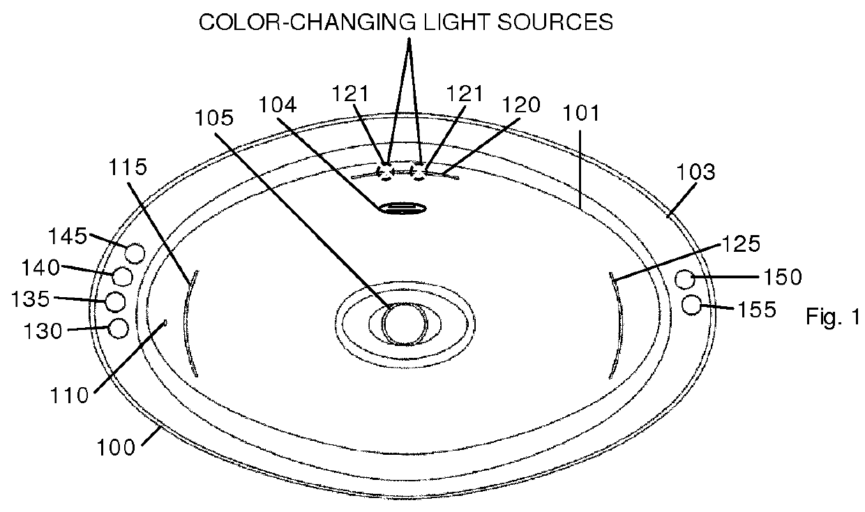
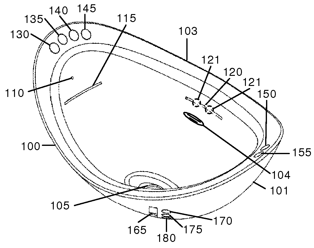
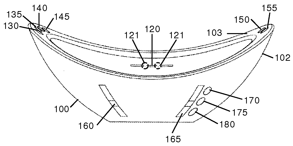
[0037]FIGS. 1 through 3 are top, front perspective, and side perspective views of a sink according to one aspect of a first embodiment. The sink comprises a bowl 100 with an exterior wall 102, an interior wall 101, an upper lip 103, an overflow drain 104, a drain 105, a plurality of generally upwardly directed orifices 110, 115, 120, and 125, and a plurality of controls and indicators 121 and 130-180. Orifice 110 is circular and is on the upper, left side of wall 101 of bowl 100; orifice 115 is an elongated slit on the left side under orifice 110, orifice 120 is an elongated slit located near the top, rear of wall 101, and orifice 125 is an elongated slit on the upper, right side of wall 101.
[0038]Walls 101 and 102 are separated by an interior space (not shown) that houses concealed plumbing and electrical connections (described below).
[0039]Controls and indicators 130-180 control the flow and temperature of water in the sink. These controls perform the follo...
all embodiments
Controls—Description and Operation—FIGS. 11 and 12
[0050]FIG. 11 is a block diagram showing connections between controls 130-180, logic circuit, and valves according to the preferred embodiment. Plumbing connections are shown in heavy lines; electrical connections are shown in lighter lines.
[0051]An electrical source 1100 is connected to power mains (not shown), or to batteries or a combination thereof. Source 1100 is preferably electrically isolated from the mains and has at least one output terminal grounded to earth in order to prevent the possibility of electrical shock to the user while operating the sink. Logic circuit 1105 is powered by source 1100 and controls all functions of the sink by receiving commands from a user through controls 130-180 and issuing commands to valves 1120, 1125, 1135-1145, and controls and indicators 130-180. Circuit 1105 is preferably a microprocessor, but can be combinatorial logic, or a field-programmable logic array. Circuit 1105 includes well-know...
PUM
 Abstract
Description
Claims
Application Information
 - R&D Engineer
- R&D Manager
- IP Professional
- Industry Leading Data Capabilities
- Powerful AI technology
- Patent DNA Extraction
Browse by: Latest US Patents, China's latest patents, Technical Efficacy Thesaurus, Application Domain, Technology Topic, Popular Technical Reports.
© 2024 PatSnap. All rights reserved.Legal|Privacy policy|Modern Slavery Act Transparency Statement|Sitemap|About US| Contact US: help@patsnap.com