Lighting system using multiple colored light emitting sources and diffuser element

a technology of diffuser element and light source, which is applied in the direction of luminescence, light source combination, instruments, etc., can solve the problems of decreasing visible spectrum return, less efficiency, and inefficient current state of phosphor-converted white led (pc-led) technology

Active Publication Date: 2010-11-23
RENESSELAER POLYTECHNIC INST
View PDF40 Cites 99 Cited by
  • Summary
  • Abstract
  • Description
  • Claims
  • Application Information

AI Technical Summary

Problems solved by technology

Due to their long operation (burn) time and low power consumption, solid state light emitting devices frequently provide a functional cost benefit, even when their initial cost is greater than that of conventional lamps.
Current state of the art phosphor-converted white LED (pc-LED) technology is inefficient in the visible spectrum.
More particularly, the LED device becomes less efficient when heated to a temperature greater than 100° C., resulting in a declining return in the visible spectrum.

Method used


Image

  • Lighting system using multiple colored light emitting sources and diffuser element
  • Lighting system using multiple colored light emitting sources and diffuser element
  • Lighting system using multiple colored light emitting sources and diffuser element

Examples


Embodiment Construction

[0054]Although the invention is illustrated and described herein with reference to specific embodiments, the invention is not intended to be limited to the details shown. Rather, various modifications may be made in the details within the scope and range of equivalents of the claims and without departing from the invention.

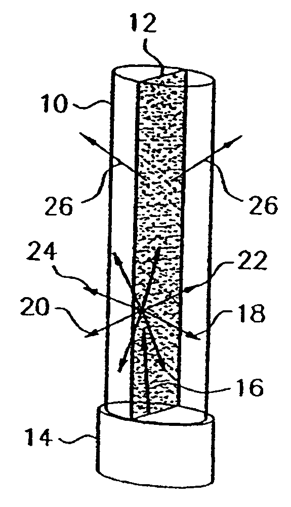
[0055]FIG. 14 is a diagram illustrating the exemplary radiation rays that may result when an exemplary radiation ray 2000 from a short-wavelength LED chip 2002 impinges on a layer of down conversion material 2004 which may be a phosphor layer. The impingement of exemplary short-wavelength radiation 2000 from a short-wavelength source such as an LED chip 2002 onto a down conversion material layer 2004 may produce radiation with four components: back transferred short-wavelength radiation 2006 reflected from the down conversion material layer 2004; forward transferred short-wavelength radiation 2008 transmitted through the down conversion material layer 2004; forwar...


PUM


Abstract

A light emitting apparatus has a radiation source for emitting multi-colored radiation. A diffuser material receives at least a portion of the multi-colored radiation emitted by the radiation source and converts the multi-colored radiation into forward transferred radiation and back transferred radiation. An optic device is coupled to the diffuser material and is adapted to receive the back transferred radiation and extract at least a portion of the back transferred radiation from the optic device.

Description

CROSS REFERENCE TO RELATED APPLICATIONS[0001]This application claims the benefit of priority to U.S. Provisional Application Ser. No. 60 / 568,373, filed May 5, 2004 and to U.S. Provisional Application No. 60 / 636,123 filed Dec. 15, 2004, and is a continuation-in-part application of U.S. application Ser. No. 10 / 583,105, filed Apr. 23, 2007 now U.S. Pat. No. 7,819,549, entitled “High Efficiency Light Source Using Solid-State Emitter And Down-Conversion Material,” which is the 371 National Phase of International Application No. PCT / US2005 / 015736, filed May 5, 2005, which was published in English under PCT Article 21(2) as WO 2005 / 107420 A2. The contents of all of these applications are incorporated in their entirety by reference herein.BACKGROUND OF THE INVENTION[0002]Solid state light emitting devices, including solid state lamps having light emitting diodes (LEDs) and resonant cavity LEDs (RCLEDs) are extremely useful, because they potentially offer lower fabrication costs and long ter...

Claims


Application Information

Patent Timeline
Patent Type & Authority Patents(United States)
IPC IPC(8): F21V9/16H01L33/50
CPCF21K9/00F21V9/16F21K2/00H01L25/0753H01L33/507H01L2933/0091H01L2924/0002H01L2924/00F21K9/64F21Y2115/30H01L33/508H01L33/58F21Y2115/10F21V9/45F21V9/38F21V5/004F21V9/32F21V13/14F21V9/08F21V3/02F21V7/06F21V9/30F21Y2113/13
Inventor NARENDRAN, NADARAJAHGU, YIMIN
Owner RENESSELAER POLYTECHNIC INST
Why Eureka
Try Eureka