Forming display color image

a color image and display technology, applied in the field of color images, can solve the problems of loss of overall display efficiency, not all of the light of undesired polarization is recycled, and not all of the recycled light exits, so as to enhance the color gamut of the display, greatly increase the display brightness, and enhance the viewing brightness

Inactive Publication Date: 2007-03-08
EASTMAN KODAK CO
View PDF8 Cites 103 Cited by
  • Summary
  • Abstract
  • Description
  • Claims
  • Application Information

AI Technical Summary

Benefits of technology

[0013] It is an advantage of the present invention to use a pixelated two-dimensional vertical cavity surface emitting laser (VCSEL) array as the light source for a display. Each color element contains thousands of micron-sized laser pixels, which are mutually incoherent. This leads to each color element producing multimode laser light. As a result of the pixel size being 3 to 5 microns in diameter, the divergence angle of the multimode laser light is on the order of 3-5°. This small divergence angle enables a 1:1 correspondence between the laser's color elements and a suitable optical switch. Correspondingly, it is no longer necessary to include a color ...

Problems solved by technology

Correspondingly, this absorption of light outside of each pixel's transmission spectra results in a loss of overall display efficiency.
However, not all of the light of the undesired polarization is recycled and not all of the recycled light exits the BLU with the correct polarization state.
As a result, unpolarized BLU light results in nearly a factor of two efficiency loss upon passing through the bottom polarizer.
However, LCD's suffer from poor contrast ratios at larger viewing angles.
Unless the contrast ratio is improved at large viewing angles, the penetration of LCDs into certain markets will be limited.
The poor contrast ratio is typically due to increased brightness of the display's dark state.
However, these methods improve the hue shift and contrast ratio only slightly and for a limited viewing cone....

Method used


Image

  • Forming display color image
  • Forming display color image
  • Forming display color image

Examples


Embodiment Construction

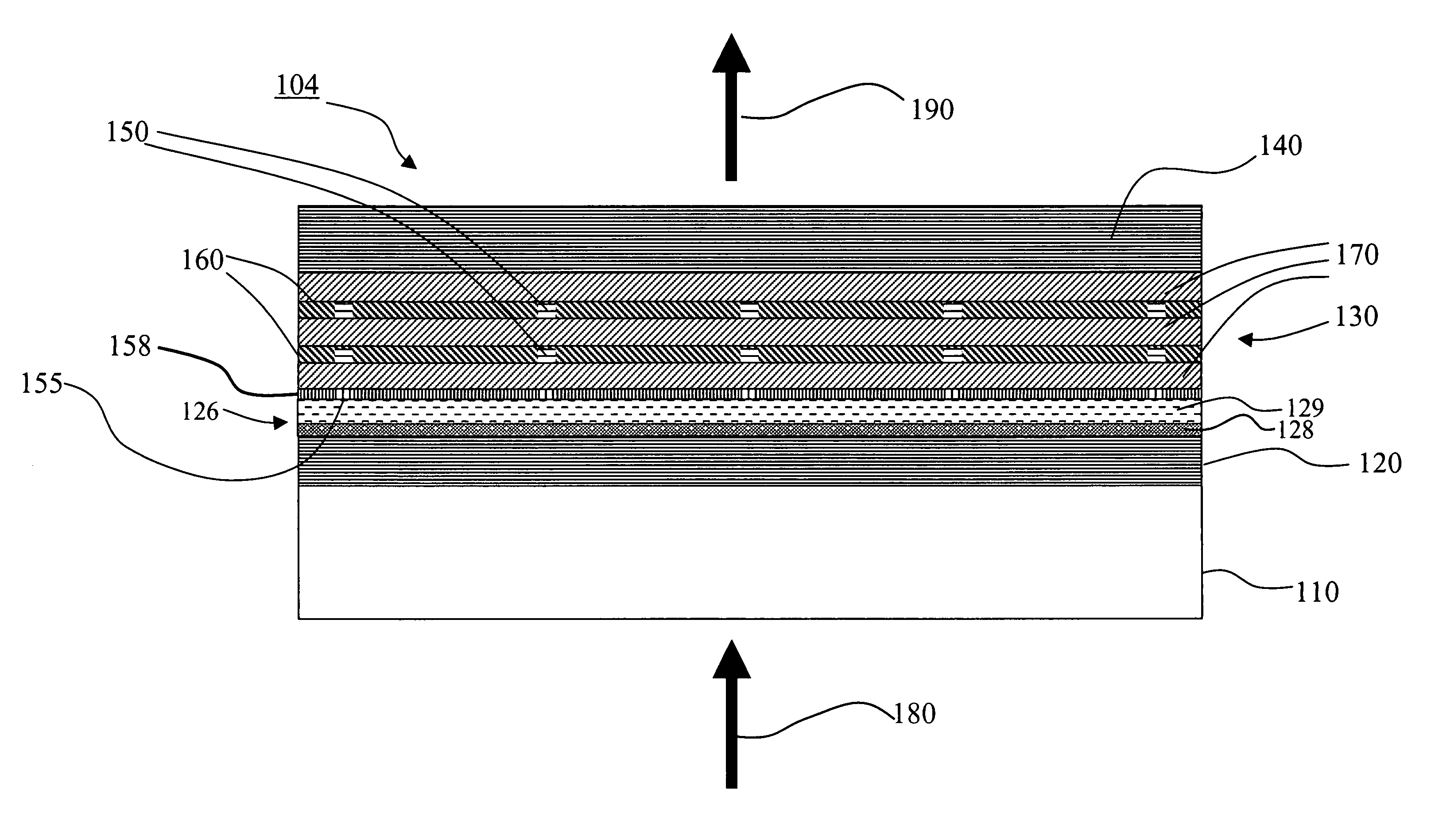
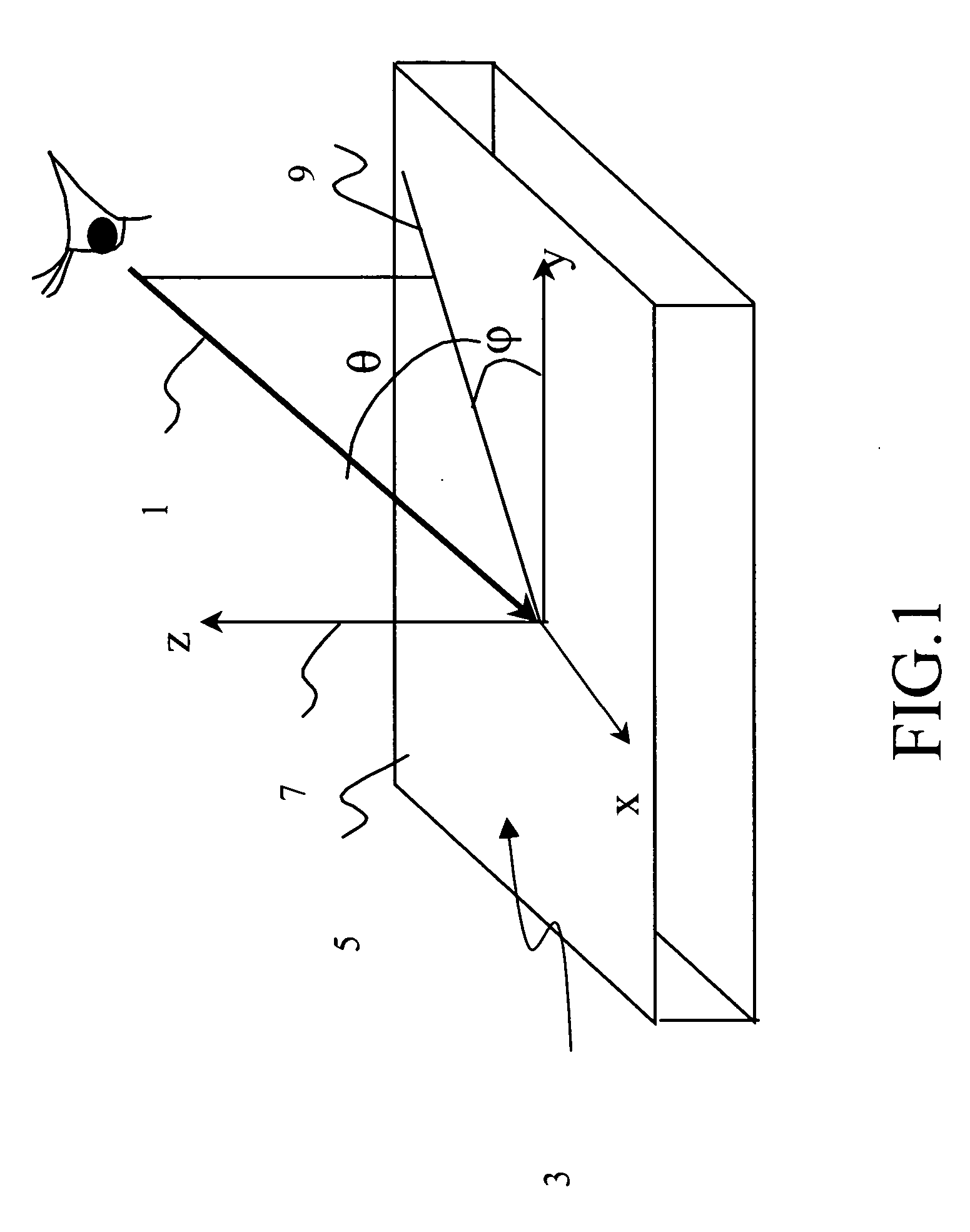
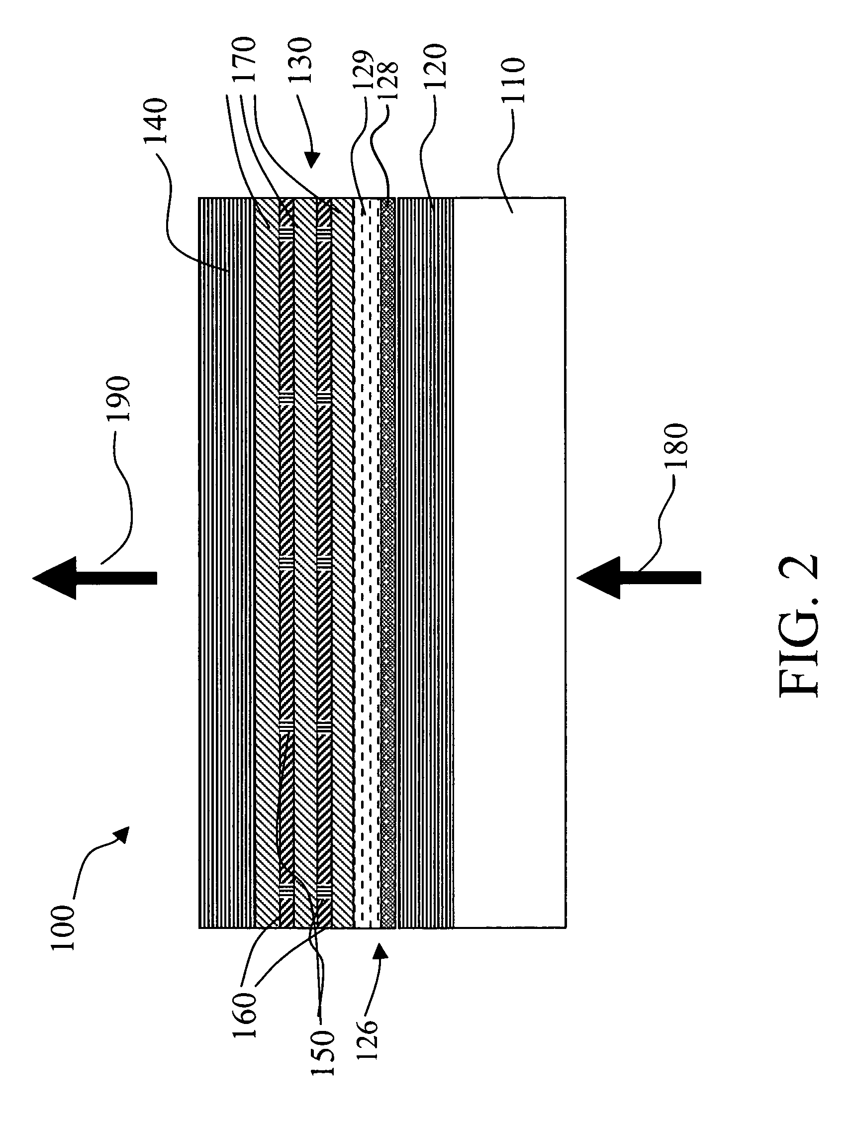
[0037] In order to facilitate reading of the specification, the following terms are defined. Optic axis herein refers to the direction in which propagating light does not see birefringence. Polarizer and analyzer herein refer to elements that polarize electromagnetic waves. However, the one closer to the source of the light will be called a polarizer although the one closer to the viewer will be called an analyzer. Polarizing elements herein refers to both the polarizer and analyzer. Azimuthal angle φ and tilt angle θ are herein used to specify the direction of an optic axis. For the transmission axes of the polarizer and the analyzer, only the azimuthal angle φ is used, as their tilt angle θ is zero.

[0038]FIG. 1 shows the definition of the azimuthal angle φ and tilt angle θ to specify the direction of the optic axis 1 with respect to the x-y-z coordinate system 3. The x-y plane is parallel to the display surface 5, and the z-axis is parallel to the display normal direction 7. The ...


PUM


Abstract

An apparatus for forming a colored image on a display, includes a VCSEL array device having a plurality of light-emitting pixels wherein each light-emitting pixel produces a beam of light including substantial components in a portion of the visible spectrum so that different light-emitting pixels produce different colored light; and a light shutter layer for each light-emitting pixel providing a modulator disposed in the path of the corresponding light beam for selectively passing corresponding colored light for providing a colored light image on the display.

Description

CROSS REFERENCE TO RELATED APPLICATIONS [0001] Reference is made to commonly assigned U.S. patent application Ser. No. 10 / 857,508, filed May 28, 2004, by Keith B. Kahen and Erica N. Montbach, entitled “DISPLAY DEVICE USING VERTICAL CAVITY LASER ARRAYS”, and commonly assigned U.S. patent application Ser. No. 10 / 857,512 filed May 28, 2004 by Keith B. Kahen and Erica N. Montbach, entitled “VERTICAL CAVITY LASER PRODUCING DIFFERENT COLOR LIGHT”, the disclosures of which are herein incorporated by reference.FIELD OF THE INVENTION [0002] The present invention relates to forming a color image using a light source and a modulator. BACKGROUND OF THE INVENTION [0003] There are a number of ways of producing pixelated colored light for display applications, such as for example, using a conventional passive or active matrix organic light emitting diode (OLED) device. Another way is to employ a liquid crystal display (LCD). In typical LCD systems, a liquid crystal cell is placed between a pair of...

Claims


Application Information

Patent Timeline
IPC IPC(8): G09G3/36
CPCG02B26/005G02B27/48G02F2203/34G02F2203/12G02F1/133603
Inventor MONTBACH, ERICA N.KAHEN, KEITH B.
Owner EASTMAN KODAK CO
Why Eureka
Try Eureka