Supercharge Your Innovation With Domain-Expert AI Agents!

Variable radius multi-lamp illumination system

a multi-lamp, variable-radius technology, applied in lighting and heating apparatus, instruments, lighting support devices, etc., can solve the problems of preventing the placement of larger devices, no flexibility in changing the area of the illuminated field, etc., and achieve the effect of optimal lighting

Active Publication Date: 2016-01-05
THE GOVERNMENT OF THE US SEC THE AIR FORCE
View PDF5 Cites 5 Cited by
  • Summary
  • Abstract
  • Description
  • Claims
  • Application Information

AI Technical Summary

Benefits of technology

The present invention provides an illumination system for optical interactions with targets. The system includes a frame with an un-impeded, pass-through opening and a plurality of electric lamps mounted on lamp pulleys. The lamps can be moved synchronously to illuminate the target surface. The lamps can also be oriented in an octagon shape to ensure optimal lighting of the target. The system allows for optical interaction between targets and an optical device located behind or within the frame. The layout of the system ensures that the lamps are positioned in a way that allows for maximum interaction with the target. The system is easy to install and adjust for different needs.

Problems solved by technology

There are several disadvantages to this design.
Firstly, although it is desirable to adjust the area being illuminated, the lamps cannot be moved, so there is no flexibility to change the area of the illuminated field.
Secondly, the lamps themselves oftentimes block the line of sight for optical devices through the frame towards the target, or prevent the placement of larger devices that would otherwise fit within the frame.

Method used


Image

  • Variable radius multi-lamp illumination system
  • Variable radius multi-lamp illumination system
  • Variable radius multi-lamp illumination system

Examples


Embodiment Construction

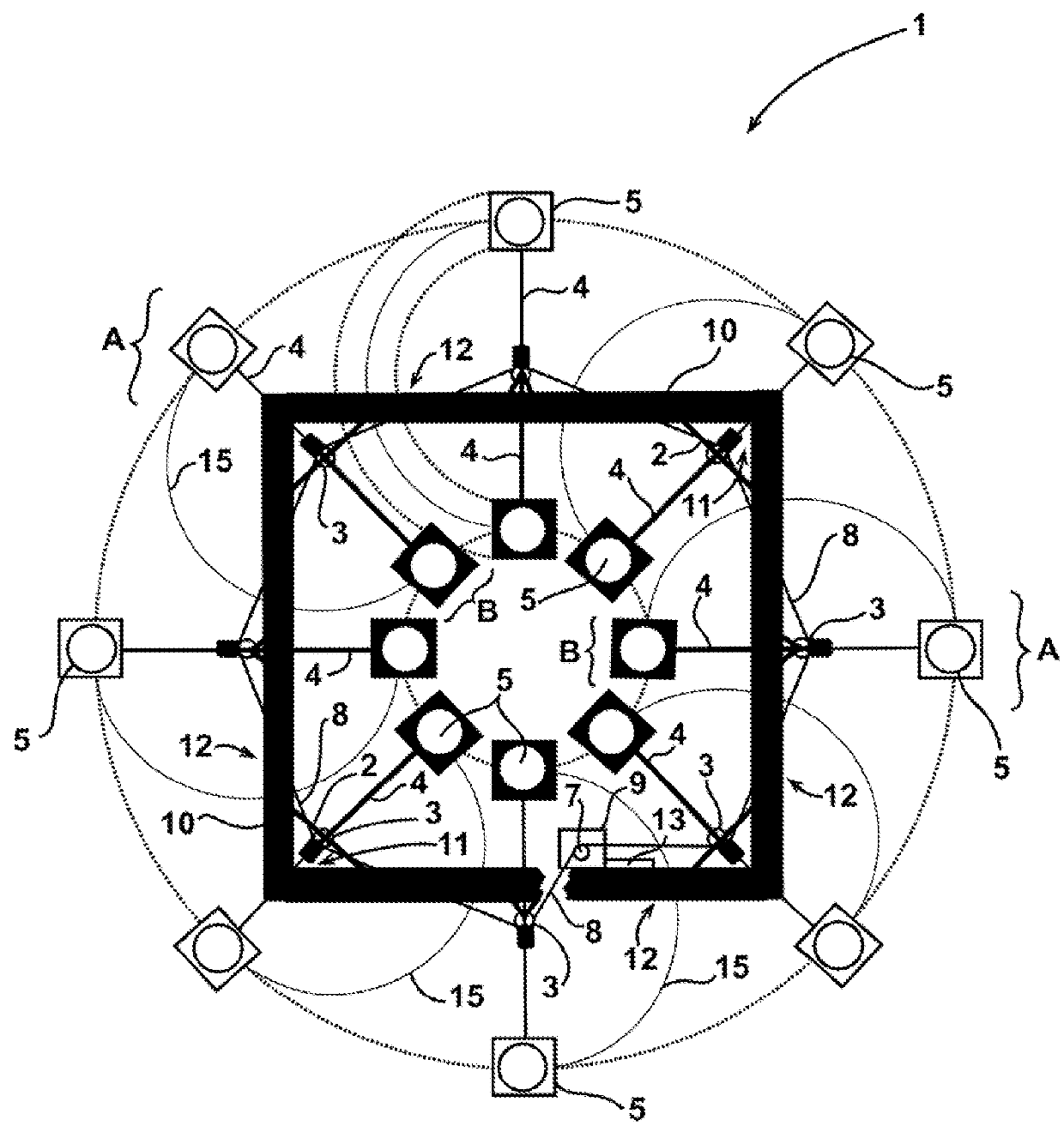
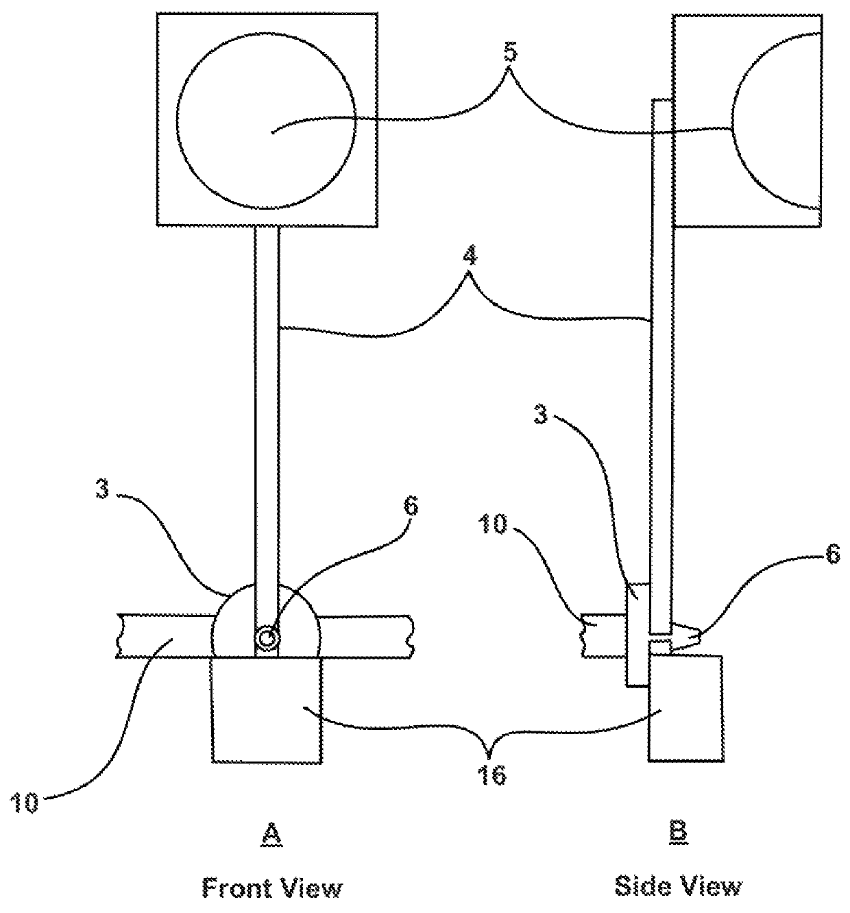
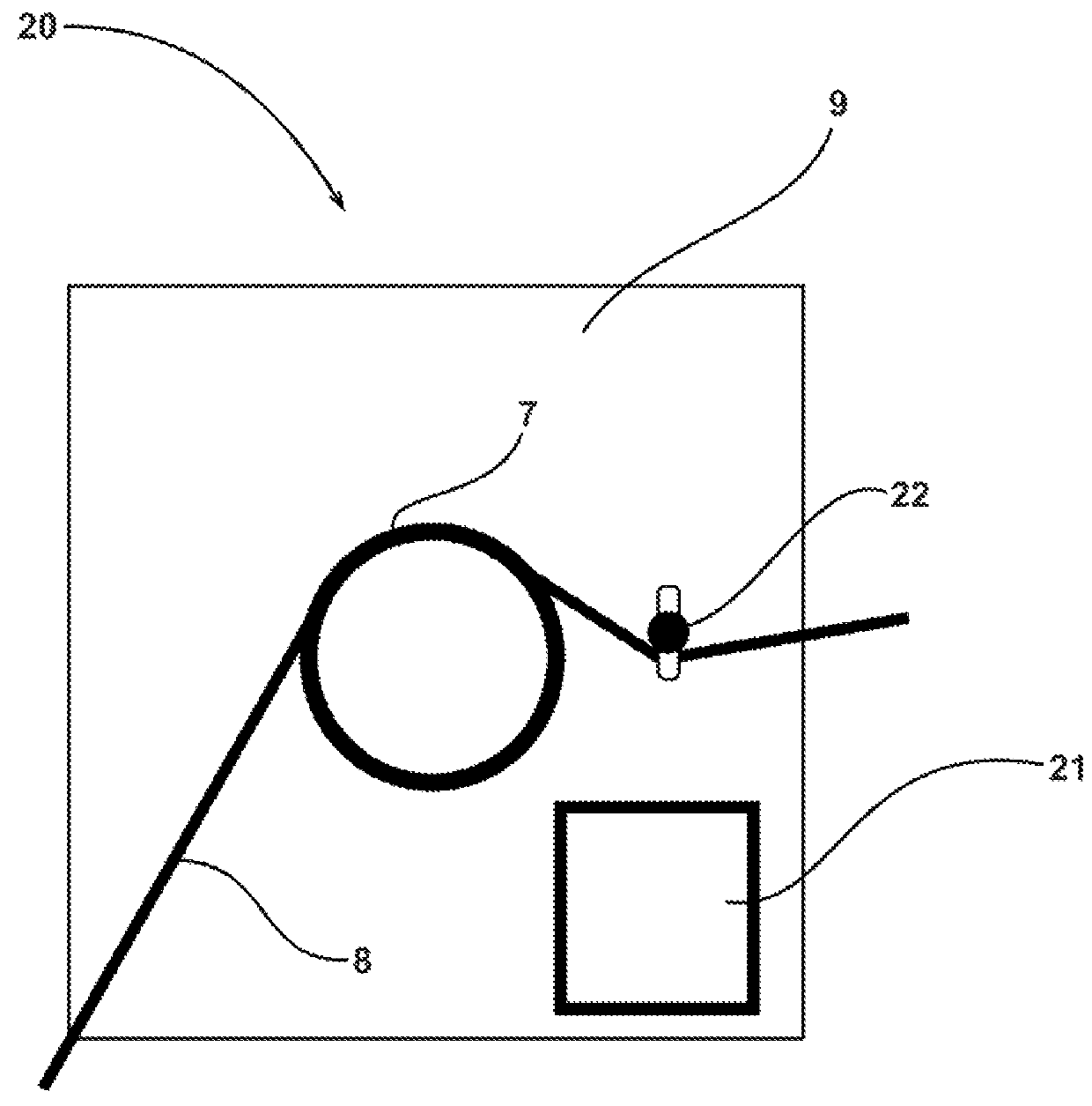
[0017]Referring to FIG. 1, a frame and lighting apparatus 1 in accordance with features of the present invention is shown. A preferred structure for the present invention comprises eight electric lamps 5 that are each mounted by lamp arms 4 to belt-driven lamp pulleys 3, which are each attached to a square framed hardware system 10 (hereinafter frame 10) such that mounted lamps 5 form an octagon shape. The octagon shape is revealed if imaginary straight lines were drawn to connect each lamp 5 with its adjacent lamp 5. Lamps 5 disposed in this configuration provide optimal illumination of a surface given the overlapping coverage of the lighting footprints provided by lamps 5. A belt 8 is mounted outside of each lamp pulley 3, and is further mounted to a motor pulley 7 that is coupled to a motor 9 that can also be mounted to the frame 10.

[0018]By means of frictional contact between belt 8, lamp pulleys 3, and motor pulley 7, the motor 9 can cause the belt 8 to move forward and backwar...


PUM


Abstract

Electric lamps are mounted by lamp arms to lamp pulleys that are, in turn, mounted to a rigid frame. A motor-driven belt synchronously rotates the lamps via frictional contact with the lamp pulleys to position the lamps to optimally illuminate a target surface. The lamps can be synchronously moved from a first location outside the periphery of the frame to a second location within the frame periphery by operation of the motor driving the belt. In either location, as well as in any other location, the apparatus provides an un-impeded, pass-through opening within the frame for an un-impeded line of sight to the target surface. Furthermore, the radial distance from each lamp to the geometric center of the frame remains the same, and the lamps remain spaced equally apart from each other.

Description

CROSS-REFERENCE TO RELATED APPLICATION[0001]This application claims priority as the beneficiary of U.S. Provisional Patent Application Ser. No. 61 / 778,404, filed Mar. 12, 2013, titled “Variable Radius Eight Lamp System,” which is hereby incorporated by reference in its entirety.STATEMENT OF GOVERNMENT RIGHTS[0002]The conditions under which this invention was made are such as to entitle the Government of the United States, as represented by the Air Force, to the entire right, title and interest therein, including foreign rights, as provided under Paragraph I(a) of Executive Order 10096.FIELD OF THE INVENTION[0003]The present invention is generally related to systems for illuminating surfaces with accuracy and consistency for interaction with optical devices (e.g., cameras and sensors). More particularly, the present invention is related to a frame and lighting system usable for target illumination that includes electric lamps mounted to lamp pulleys that are in turn mounted to a fram...

Claims


Application Information

Patent Timeline
IPC IPC(8): F21V21/30F21V21/26F21V8/00F21V21/16
CPCF21V21/30G02B6/0076G02B6/0075F21V21/16F21V21/26F21V21/20
Inventor INBODY, WILLA, CATHER
Owner THE GOVERNMENT OF THE US SEC THE AIR FORCE
Features
  • R&D
  • Intellectual Property
  • Life Sciences
  • Materials
  • Tech Scout
  • Unparalleled Data Quality
  • Higher Quality Content
  • 60% Fewer Hallucinations
Learn More