Battery device

a battery device and battery technology, applied in the direction of battery/cell propulsion, hybrid vehicles, cell components, etc., can solve the problems of increasing the stiffness of the frame structure and the battery device, and the battery module cannot be used to stiffen the frame structure, so as to achieve the effect of protection

Active Publication Date: 2016-01-05
DR ING H C F PORSCHE AG
View PDF14 Cites 18 Cited by
  • Summary
  • Abstract
  • Description
  • Claims
  • Application Information

AI Technical Summary

Benefits of technology

[0010]The invention relates to a battery device that has interconnected battery modules oriented parallel to one another and cooling plates arranged between the battery modules. Each cooling plates is formed from two metal layers that are connected to one another. The cooling plates are traversed by a flow of fluid and have ends that are connected fixedly to a frame structure of a housing of the battery device for stiffening the frame structure. Thus, the battery device is encased by a housing that has the frame structure, and the individual cooling plates are connected to the frame structure, for example by screws, to stiffen the frame structure. The battery modules are arranged between the individual cooling plates and each battery module has multiple battery cells. The battery modules are in direct or at least heat-transmitting contact with the cooling plates. A direct connection of the individual battery modules to the frame structure may be provided, but is not imperative. The battery modules expand and contract due to temperature changes that arise during use of the battery device. Therefore the battery modules cannot be used for stiffening the frame structure and could be damaged if connected fixedly to the frame structure. However, each cooling plate is formed from at least two metal layers that are connected to one another, and hence the cooling plates are highly stiff, thereby increasing the stiffness of the frame structure and the battery device. Furthermore, fluid flows through the cooling plates to achieve effective cooling of the individual battery modules arranged between the cooling plates so that the battery modules can be operated at their maximum power for long periods.
[0011]The two metal layers of at least one cooling plate may be formed from steel or from aluminum. Steel is a relatively stiff material and, due to its high inherent stiffness, is particularly preferable for stiffening the battery device. Steel also is a good heat conductor and can impart a high cooling action to the battery modules to be cooled. Forming the two layers of at least one cooling plate from aluminum also stiffens the battery device. Aluminum also is considerably lighter than steel and contributes to an increased range of travel in motor vehicles operated purely by electric motor. Furthermore, aluminum has high thermal conductivity for achieving good heat transfer and good cooling of the battery modules.
[0013]A housing shell preferably surrounds the frame structure and may be formed from plastic or metal, such as steel or aluminum. The housing shell protects the individual battery modules from dirt, which is highly advantageous if the battery device is mounted on an underside of a motor vehicle and is exposed directly there to dirt from the road. A housing shell composed of plastic is lightweight, which is highly advantageous in the case of electric or hybrid vehicles, offers a certain level of protection against stone impact, and is resistant to corrosion, which is a considerable advantage for a battery device installed on the underside of the motor vehicle.
[0014]The invention also relates to a motor vehicle that has an electric motor and is equipped with the above-described battery device. The housing shell of the battery device preferably is matched to a shape of an underside of the motor vehicle. In this way, it is possible to attain a form-fitting arrangement, which is optimized with regard to installation space of the battery device underneath the motor vehicle. The housing shell preferably is formed from a hard plastic and can withstand the loads occurring at that location without problems. The battery modules are arranged within the housing shell so that the greatest possible number of battery modules is accommodated in a housing shell of the smallest possible volume.

Problems solved by technology

Therefore the battery modules cannot be used for stiffening the frame structure and could be damaged if connected fixedly to the frame structure.
However, each cooling plate is formed from at least two metal layers that are connected to one another, and hence the cooling plates are highly stiff, thereby increasing the stiffness of the frame structure and the battery device.

Method used


Image

  • Battery device
  • Battery device
  • Battery device

Examples


Embodiment Construction

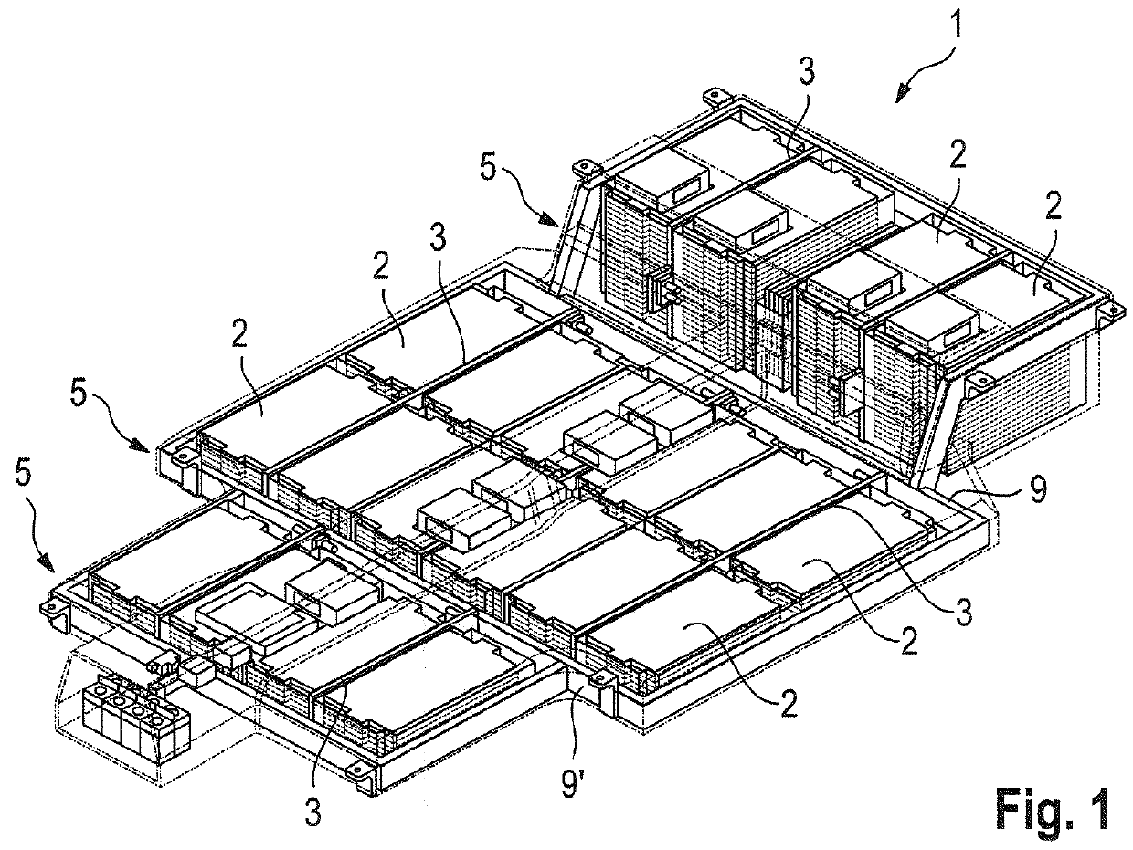
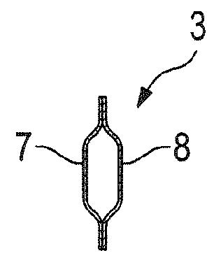
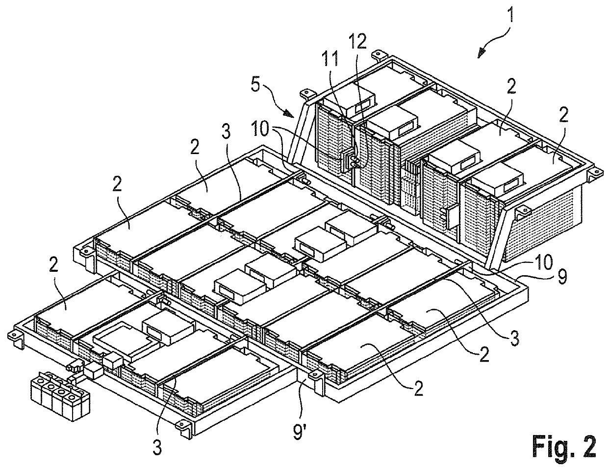
[0023]A battery device according to the invention is identified by the numeral 1 in FIGS. 1 and 2. The battery device 1 has multiple interconnected battery modules 2, each of which has a plurality of individual battery cells. A cooling plate 3 is arranged between at least two of said battery modules 2, and a fluid flows through the cooling plate 3 for cooling the battery modules 2. A housing 4 encases the battery device 1, as shown in FIG. 3, and is composed substantially of a frame structure 5 and a housing shell 6 that encases said frame structure 5. The cooling plate 3 is formed from two metal layers 7 and 8 that are connected to one another, as shown in FIG. 1. Furthermore, ends of the cooling plates 3 are connected fixedly to the frame structure 5 for stiffening the frame structure 5. As shown in FIG. 2, ends of the cooling plate 3 are connected to frame parts 9 or 9′ of the frame structure 5 and thus stiffen the frame parts 9, 9′ with respect to one another. The cooling plate ...


PUM

PropertyMeasurementUnit
shapeaaaaaaaaaa
surface areasaaaaaaaaaa
inherent stiffnessaaaaaaaaaa

Abstract

A battery device has at least two interconnected battery modules and at least one cooling plate arranged between two battery modules for cooling the battery modules. A housing encases the battery device and is provided with a frame structure. The at least one cooling plate is traversed by a flow of fluid and is formed from two metal layers that are connected to one another. Additionally, the at least one cooling plate is connected fixedly at least by its ends to the frame structure and stiffens the frame structure. Thus, the battery device exhibits high power and is robust.

Description

CROSS REFERENCE TO RELATED APPLICATION[0001]This application claims priority under 35 USC 119 to German Patent Appl. No. 10 2012 108 762.8 filed on Sep. 18, 2012, the entire disclosure of which is incorporated herein by reference.BACKGROUND[0002]1. Field of the Invention.[0003]The invention relates to a battery device having at least two interconnected battery modules and having at least one cooling plate arranged between two battery modules. The present invention also relates to a motor vehicle having a battery device of said type.[0004]2. Description of the Related Art.[0005]U.S. 2011 / 0212355 A1 discloses a generic battery device having a plurality of interconnected battery modules and cooling plates arranged between the battery modules for the purpose of cooling the battery modules.[0006]U.S. 2011 / 0162821 A1 discloses a cooling system for cooling solar cells.[0007]U.S. Pat. No. 6,821,671 B2 discloses a battery device having a plurality of battery modules or battery cells. Cooling...

Claims


Application Information

Patent Timeline
Patent Type & Authority Patents(United States)
IPC IPC(8): H01M10/613H01M2/10B60L11/18H01M10/625H01M10/647H01M10/6556B60L50/64
CPCH01M10/613B60L11/1879H01M2/1077H01M2/1083H01M10/625H01M10/647H01M10/6556Y02T10/705Y02T10/7005Y10S903/907H01M50/227H01M50/224B60L50/64H01M50/204H01M50/249Y02T10/70Y02E60/10H01M10/627H01M50/20
Inventor SCHMIDT, TIMLUZ, DIETMARHENGER, NIKOLAICURNOW, JEREMY
Owner DR ING H C F PORSCHE AG
Why Eureka
Try Eureka