
Non-drip, direct-flow connectors with secure locking

a technology of direct-flow and connectors, applied in the direction of pipe joints, couplings, thin material handling, etc., can solve the problems of users or patients being exposed to danger

Active Publication Date: 2016-01-12
VYGON SA
View PDF13 Cites 30 Cited by
  • Summary
  • Abstract
  • Description
  • Claims
  • Application Information

AI Technical Summary

Benefits of technology

The invention proposes a new assembly of male and female connectors that can be securely connected for a fluid circuit. The components of the assembly are perfectly cleanable, which minimizes or eliminates the formation of drops when the connectors are separated. Additionally, this type of connector assembly reduces risks associated with deterioration of the fluids passing through it, such as the possibility of damaging red blood cells.

Problems solved by technology

Indeed, the products transferred through these connectors are generally more or less dilute medicines, which can therefore be dangerous for exposed users or patients, as can be the case for those preparing medicines.
The formation of drops at the outlet of the connectors can also be the source of cross-contamination in the preparation of the medicines themselves.

Method used


Image

  • Non-drip, direct-flow connectors with secure locking
  • Non-drip, direct-flow connectors with secure locking
  • Non-drip, direct-flow connectors with secure locking

Examples


Embodiment Construction

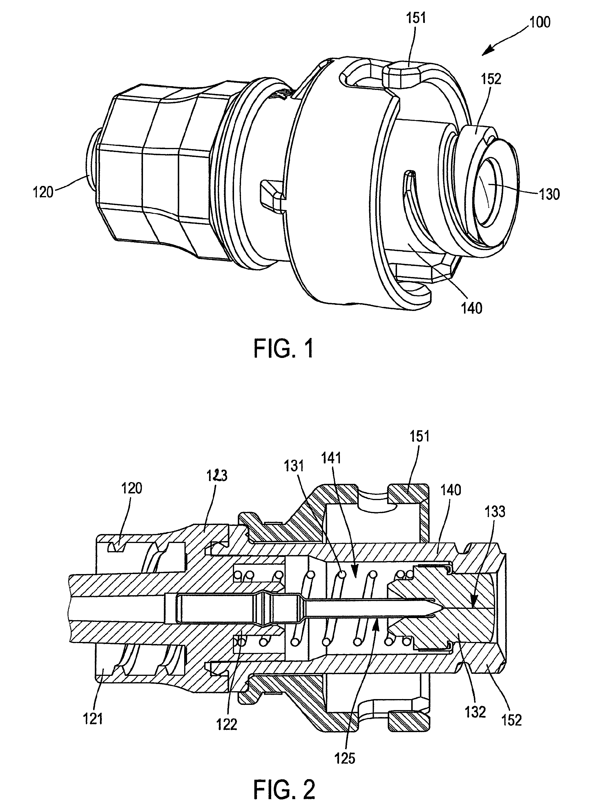
[0076]Referring to FIGS. 1 and 2, we will first of all describe a female connector 100 according to the invention.

[0077]The female connector 100 comprises a proximal hub 120, an elastically deformable, substantially tubular membrane 130 and a distal hub 140 attached to the proximal hub 120.

[0078]The proximal hub 120 has a generally tubular shape and comprises a proximal end which includes, here, a connectable entry 121 of the female “Luer lock” type. As a variant embodiment, this connectable entry 121 is of the male “Luer lock” type. It extends in the distal direction into a hollow body 122.

[0079]The hollow body122 of the proximal hub 120 is terminated, in the distal direction, by a circular shaped flange 123 coaxially topped by a hollow connection tube 124 which extends, protruding from the proximal hub 120 in the distal direction. The hollow tube 124 terminates in a free distal end 125 and constitutes a connection member.

[0080]We will now describe in more detail the membrane 130 o...


PUM


Abstract

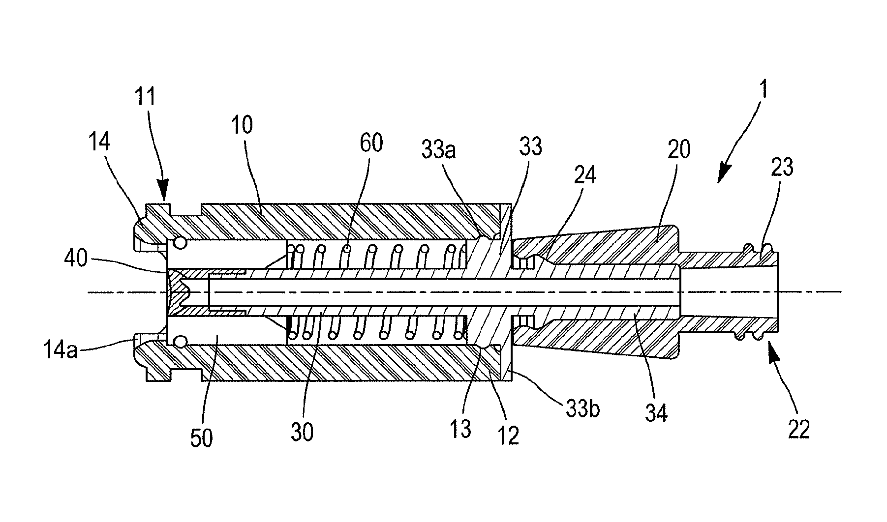
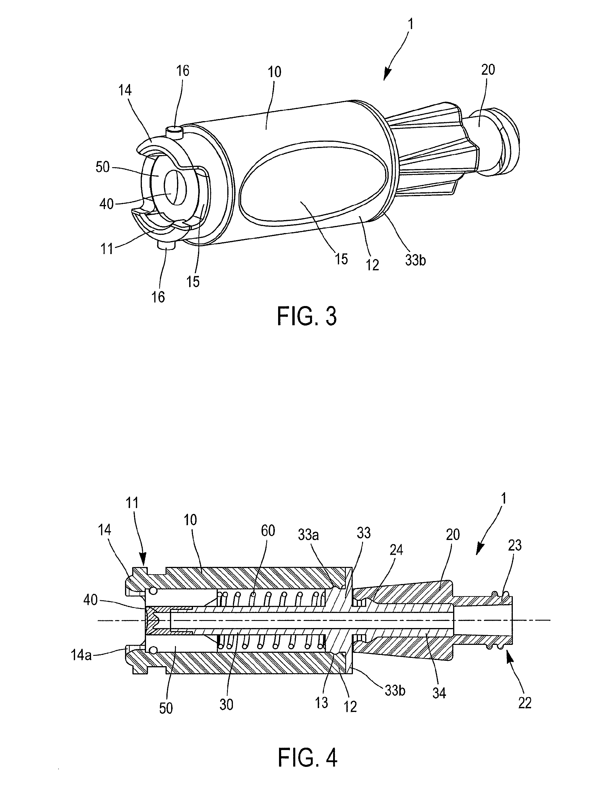
The invention relates to a male connector for a liquid circuit, comprising: a distal connection piece comprising a tubular part that defines a passage; a proximal connection piece; a joining member extending in a fixed and co-axial manner in the tubular part of the distal connection piece, the joining member being formed by a tubular body on which is fixed, at a free end, a cylindrical valve which is elastically deformable and closed at a distal end by a valve thickness traversed by a slit; and a sliding ring mounted on the tubular body, the sliding ring being movable between an inactive position, in which it encapsulates the walls of the valve, leaving the distal end of the valve free, and a connection position, in which it is situated at a distance from the distal end of the valve and exposes all or part of the lateral walls of the valve.

Description

CROSS REFERENCE TO RELATED APPLICATIONS[0001]The present application is a national phase entry under 35 U.S.C. §371 of International Application No. PCT / EP2012 / 064669, filed Jul. 26, 2012, published in French, which claims priority from French Patent Application No. 1156955, filed Jul. 29, 2011, the disclosures of which are incorporated by reference herein.BACKGROUND OF THE INVENTION[0002]The invention relates to a connector for a fluid circuit, particularly for medical use.[0003]Such a secure connector is known from document EP 0 544 581, comprising a distal entry cone of the female “Luer” type designed to be connected with a device having a compatible and complementary male “Luer” type connector. The distal entry cone is plugged by a septum or membrane having a flush surface which is easily cleanable to remove germs or bacteria prior to making a connection. The septum protects a tube which, once the connection is made, extends partially into the hole in the male “Luer” type connec...

Claims


Application Information

Patent Timeline
Patent Type & Authority Patents(United States)
IPC IPC(8): F16L37/38F16L37/02F16L29/00A61M39/10A61M39/26
CPCF16L37/02A61M39/10F16L29/005F16L37/38A61M2039/1033A61M2039/267Y10T137/9029
Inventor CARREZ, JEAN-LUCBARRE, LAURENTPECH, MARIE-HELENE
Owner VYGON SA
Learn More