Ribbon bonding in an electronic package

a technology of electronic packaging and bonding, which is applied in the direction of manufacturing tools, non-electric welding apparatus, and capacitors, etc., can solve the problems of increasing the thickness of metalized parts, increasing the cost by decreasing the throughput of wafer/die manufacturing process, and limited wires, so as to reduce processing steps and time to produce the connection, reduce the overall volume of the connection, and increase the cross section and contact area

Inactive Publication Date: 2007-06-21
ORTHODYNE ELECTRONICS
View PDF2 Cites 28 Cited by
  • Summary
  • Abstract
  • Description
  • Claims
  • Application Information

AI Technical Summary

Benefits of technology

[0016] The present invention allows using the same bonding process as with wires, i.e., an ultrasonic bonding process, increasing the cross section and contact area for the current paths while limiting or even reducing the overall volume occupied by the connection, and reducing the processing steps and time to produce the connection. Using a ribbon of the present invention allows the main loop cross section to be maximized since gaps between wires are filled. Even though the ribbon has a large cross section, the thickness can still be reduced compared to a wire, which makes bonding by ultrasonic processes less difficult. Consequently, bonding is easier, the loop height can be lowered, which results in lower interconnect height and a potential for reduced package height for smaller packages, and the ability to form the loops increases, which results in shorter loops and more stitches. Multiple stitches allow using smaller bond areas (per stitch), which alleviates the need for a heavy bond head to generate and apply high force and ultrasonic power during bonding. Thus, yields higher throughput. The use of multiple stitches, leading to shorter distances between stitches, reduces the spreading resistance, which allows higher current carrying capability.
[0017] In other embodiments, the ribbon can be bonded and cut at different angles, depending on the orientation of the contacts of the die and lead terminals. This allows optimal usage of the ribbon contact area, maximizes ribbon width, and allows placing a large ribbon in existing packages designed for round wire bonding (e.g., TO-220 packages) in an optimized manner.

Problems solved by technology

However, since semiconductor devices can be susceptible to environmental conditions, such as dust, moisture, and sudden impact, which can damage or otherwise interfere with the proper operation of the device, the device is typically protected by a die package.
However, increasing the thickness of metalized portion 22 also increases the cost by decreasing throughput of the wafer / die manufacturing process.
Further, wires are limited by their size, typically around 20 mil in diameter, which also limits the amount of current that can be carried in each wire.
Consequently, large numbers of wires are sometimes needed to make the desired connections in certain applications, which can increase the cost and decrease throughput of the interconnect process equipment (e.g., the wire bonder).
However, using a strap also has disadvantages.
These layers, which are different than the standard metalization layer, e.g., aluminum, together result in higher manufacturing cost of the metalization, and consequently of the semiconductor die.
Beside other negative effects (like corrosion in contact with humidity), their presence negatively influences the strength and reproducibility of the adhesion of the molding compound in a subsequent package encapsulation.
This again can result in a limited reliability of such parts.
However, cost effective wet chemical cleaning processes are known to offer limited process control capability, causing an increased yield loss potential, beside the additional costs (e.g., labor, floor space, equipment, consumables, and yield loss) due to the need for this additional process step.
Such a cleaning is also difficult to automate (which would reduce labor cost) and difficult to implement in a clean room environment.
Furthermore, wet chemical processes, as well as solder reflow using flux (fumes), may be environmentally unfriendly.
Two other disadvantages of a copper strap interconnect are (1) limited flexibility (since the straps are typically stamped on the die bonder, device changes which require a different strap geometry will require exchanging the stamping tool, which increases time and cost) and (2) the relatively stiff copper strap can form a significant stress on the silicon die, which can cause the die to crack, especially if the thickness of the attachment layer (e.g., solder or epoxy) is not well controlled above a certain minimum.
Solder ball based interconnects have similar disadvantages to those of the strap configuration with regards to the use of solder paste and inflexibility.
In high current applications, such a configuration has the additional disadvantage of the solder's high susceptibility to electromigration.
Consequently, bonding is easier, the loop height can be lowered, which results in lower interconnect height and a potential for reduced package height for smaller packages, and the ability to form the loops increases, which results in shorter loops and more stitches.

Method used


Image

  • Ribbon bonding in an electronic package
  • Ribbon bonding in an electronic package
  • Ribbon bonding in an electronic package

Examples


Embodiment Construction

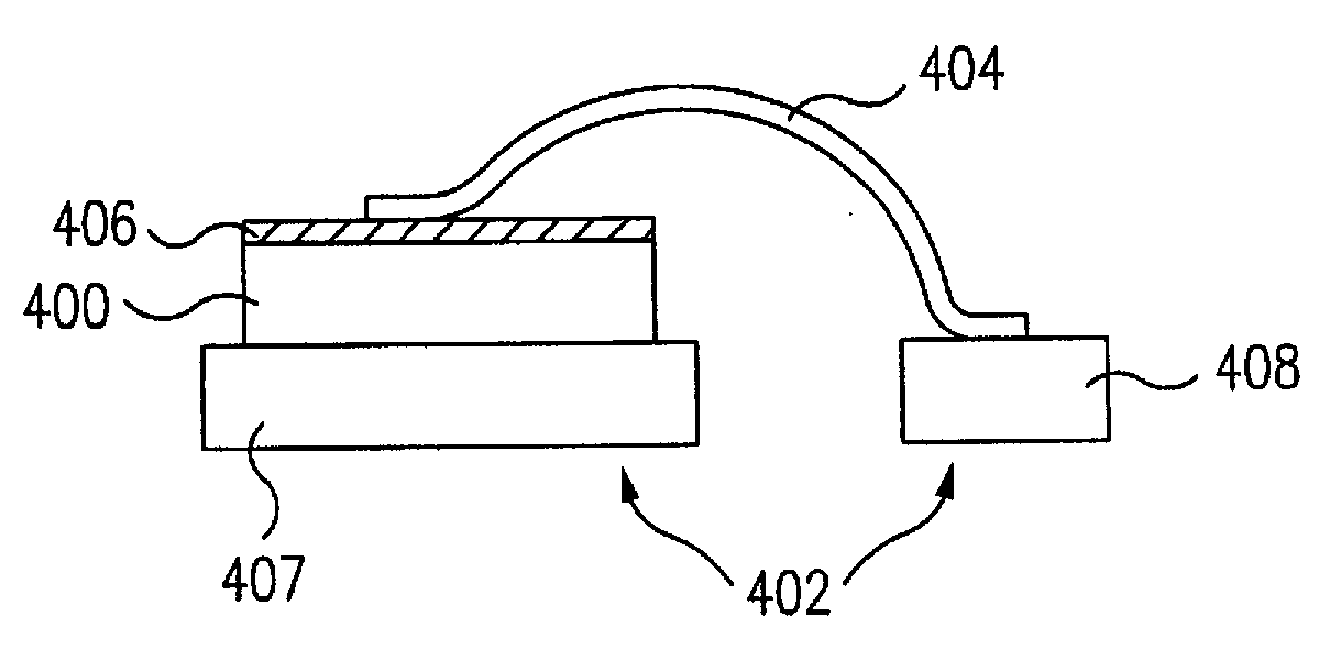
[0034] According to one aspect of the present invention, one or more conductive flexible ribbons are used to electrically connect a semiconductor die to a lead frame.

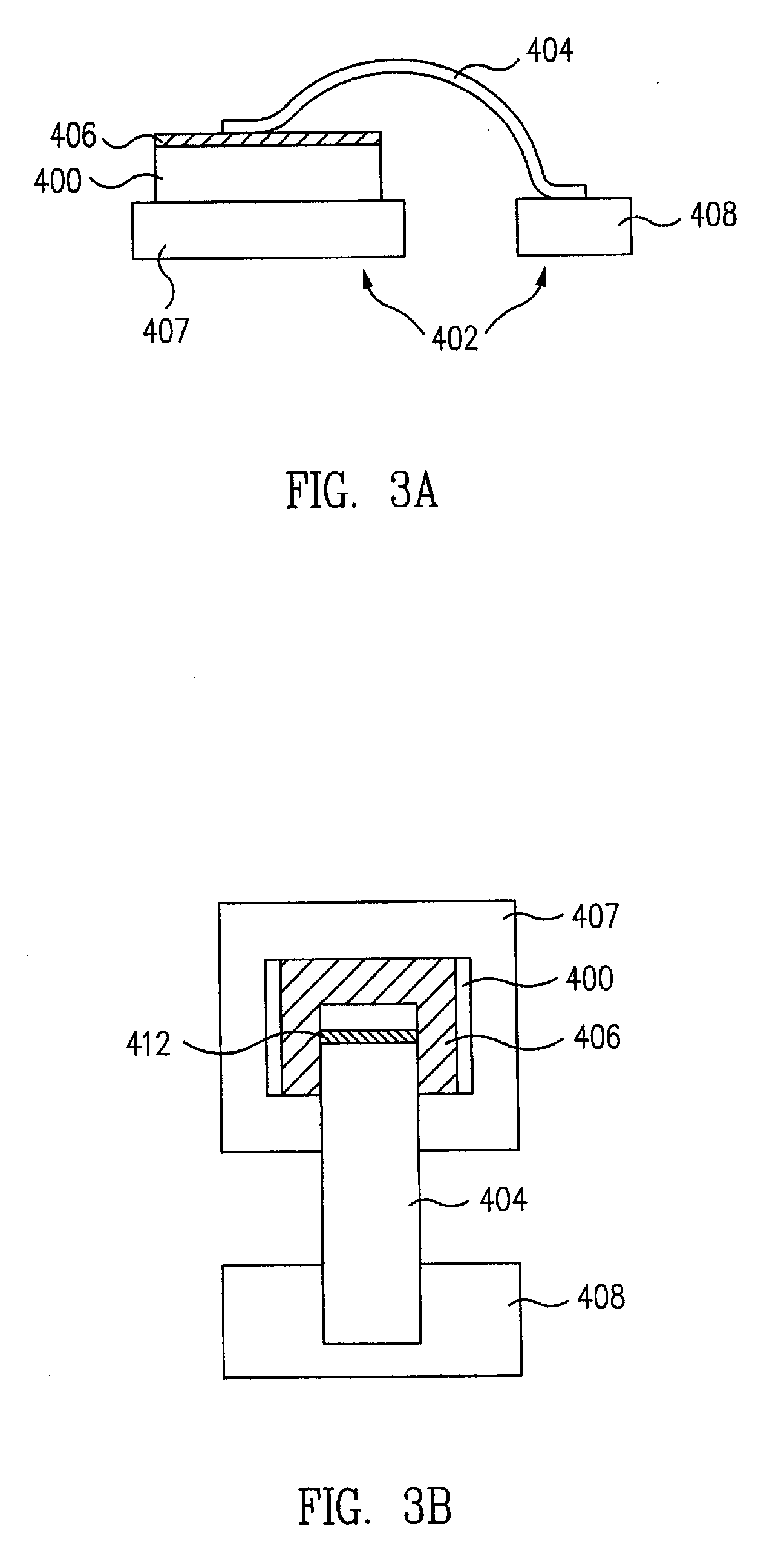
[0035]FIGS. 3A and 3B show a side view and top view of a semiconductor die 400 coupled to a lead frame 402 by a conductive flexible ribbon 404, according to one embodiment of the invention. Die 400 includes a metalized portion 406, such as aluminum, that provides connection to underlying elements of die 400. Die 400, in one embodiment, is part of a power semiconductor device, such as a power MOSFET. Lead frame 402 includes a support portion 407 to which die 400 is secured, e.g., by solder or epoxy, and terminals 408 that allow electrical connection to external devices. An enclosure, covering, or package protects the die from external elements. In some embodiments, the semiconductor package is a TO-220 or an SO-8 package.

[0036] Ribbon 404, which may have a rectangular cross section, is aluminum, although other conducti...


PUM

PropertyMeasurementUnit
thicknessaaaaaaaaaa
diameteraaaaaaaaaa
widthaaaaaaaaaa

Abstract

A flexible conductive ribbon is ultrasonically bonded to the surface of a die and terminals from a lead frame of a package. Multiple ribbons and / or multiple bonded areas provide various benefits, such as high current capability, reduced spreading resistance, reliable bonds due to large contact areas, lower cost and higher throughput due to less areas to bond and test.

Description

CROSS REFERENCE TO RELATED APPLICATIONS [0001] This is a divisional application of U.S. patent application Ser. No. 10 / 429,128, entitled “Ribbon Bonding”, filed May 2, 2003.BACKGROUND [0002] 1. Field of the Invention [0003] The present invention relates to semiconductor devices, and in particular, to interconnecting a semiconductor die to a terminal lead in a semiconductor package. [0004] 2. Related Art [0005] In the manufacture of semiconductor devices, active elements in a semiconductor device, such as drain and / or source regions in a semiconductor die, are electrically connected to other devices or electronic components, such as on a printed circuit board. However, since semiconductor devices can be susceptible to environmental conditions, such as dust, moisture, and sudden impact, which can damage or otherwise interfere with the proper operation of the device, the device is typically protected by a die package. The die package both protects the die and allows the die to electric...

Claims


Application Information

Patent Timeline
Patent Type & Authority Applications(United States)
IPC IPC(8): H01L21/00H01L21/60H01L21/607H01L23/495
CPCH01L23/4952H01L2924/1305H01L24/45H01L24/48H01L24/49H01L24/78H01L24/85H01L2224/05624H01L2224/291H01L2224/2919H01L2224/45014H01L2224/45015H01L2224/45124H01L2224/45139H01L2224/45144H01L2224/45147H01L2224/4554H01L2224/45565H01L2224/45624H01L2224/48091H01L2224/48247H01L2224/4846H01L2224/48624H01L2224/48724H01L2224/48824H01L2224/49175H01L2224/78316H01L2224/85205H01L2924/01002H01L2924/01004H01L2924/01005H01L2924/01006H01L2924/01013H01L2924/01014H01L2924/01015H01L2924/01028H01L2924/01029H01L2924/01042H01L2924/01047H01L2924/01078H01L2924/01079H01L2924/01082H01L2924/014H01L2924/10253H01L2924/13091H01L2924/19041H01L2924/19042H01L2924/20755H01L2924/30107H01L2924/00014H01L2924/01019H01L2924/01033H01L2224/45032H01L2224/48137H01L2924/20303H01L2924/20304H01L23/498H01L2224/48472H01L2224/45033H01L2924/1306H01L24/29H01L2224/45655H01L2224/45644H01L2224/45639H01L2224/45647H01L2924/0665H01L2224/78H01L2924/00H01L2924/3512H01L2924/00015H01L2924/181H01L2224/85203H01L2924/00011B23K20/008B23K2101/32B23K2101/38H01L2224/85207H01L2224/85181H01L2924/01049H01L2924/206H01L2224/43848
Inventor LUECHINGER, CHRISTOPH B.
Owner ORTHODYNE ELECTRONICS
Why Eureka
Try Eureka