
Thermal printing device for electronic voting apparatus

a printing device and electronic voting technology, applied in the direction of printing, other printing devices, instruments, etc., to achieve the effect of reducing the cost of the motor and facilitating the redirection of printed paper

Active Publication Date: 2016-01-12
APS TRADING OOD
View PDF9 Cites 1 Cited by
  • Summary
  • Abstract
  • Description
  • Claims
  • Application Information

AI Technical Summary

Benefits of technology

The invention aims to improve the loading of paper in thermal printers for voting machines. The new device is designed to be compact, secure, and easy to use, with a simple construction and minimal parts to reduce costs. In addition, a new paper exit selector means is introduced that allows for easy redirecting of printed paper and ensures the device's safety. The paper transport unit is driven by a motor through a rubber roller, which further reduces costs. Overall, the invention provides a cost-effective and efficient solution for thermal printing in voting machines.

Problems solved by technology

In such voting systems one of the main problems is paper loading that should be quick, easy and secured.

Method used


Image

  • Thermal printing device for electronic voting apparatus
  • Thermal printing device for electronic voting apparatus
  • Thermal printing device for electronic voting apparatus

Examples


Embodiment Construction

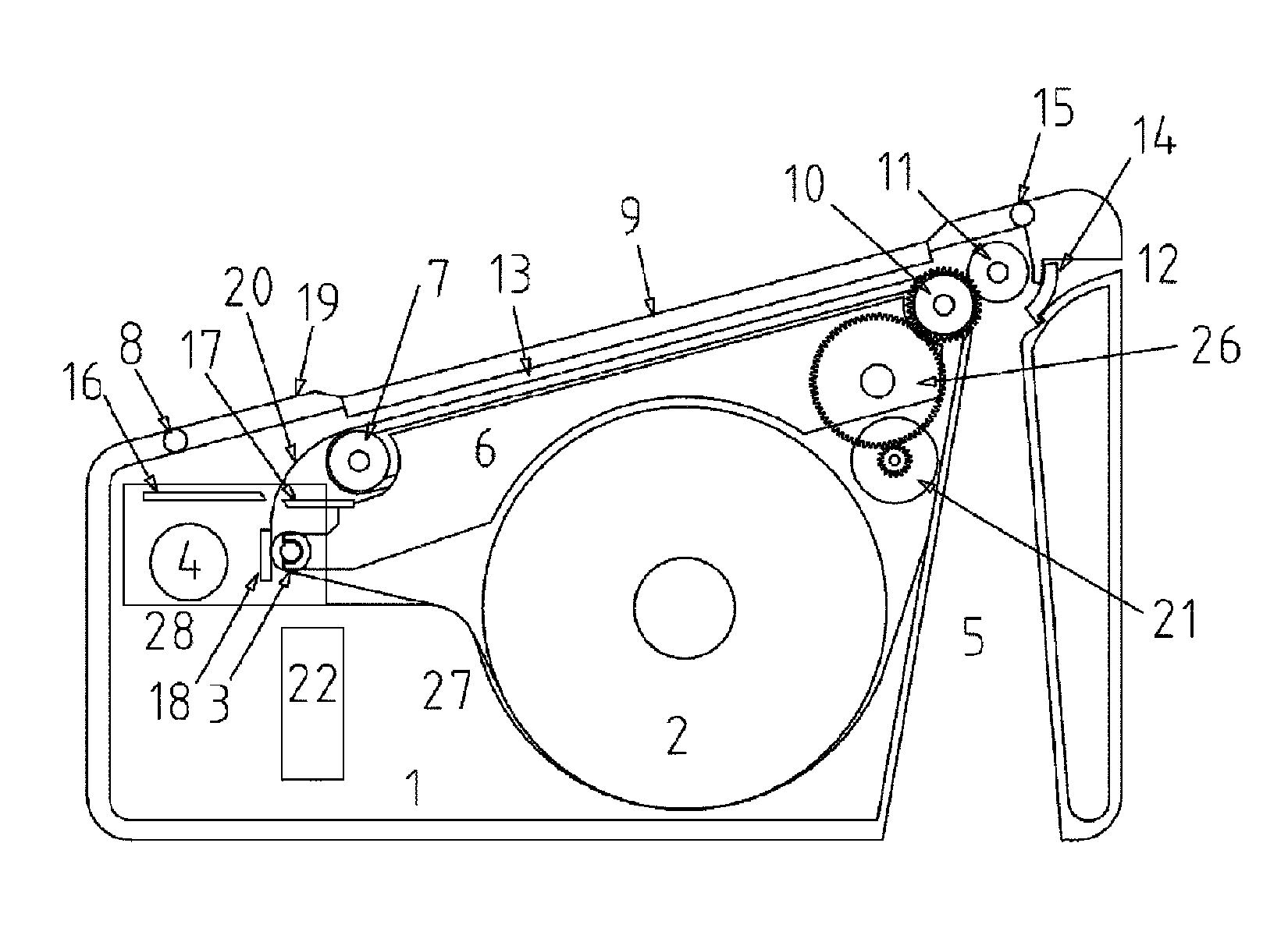
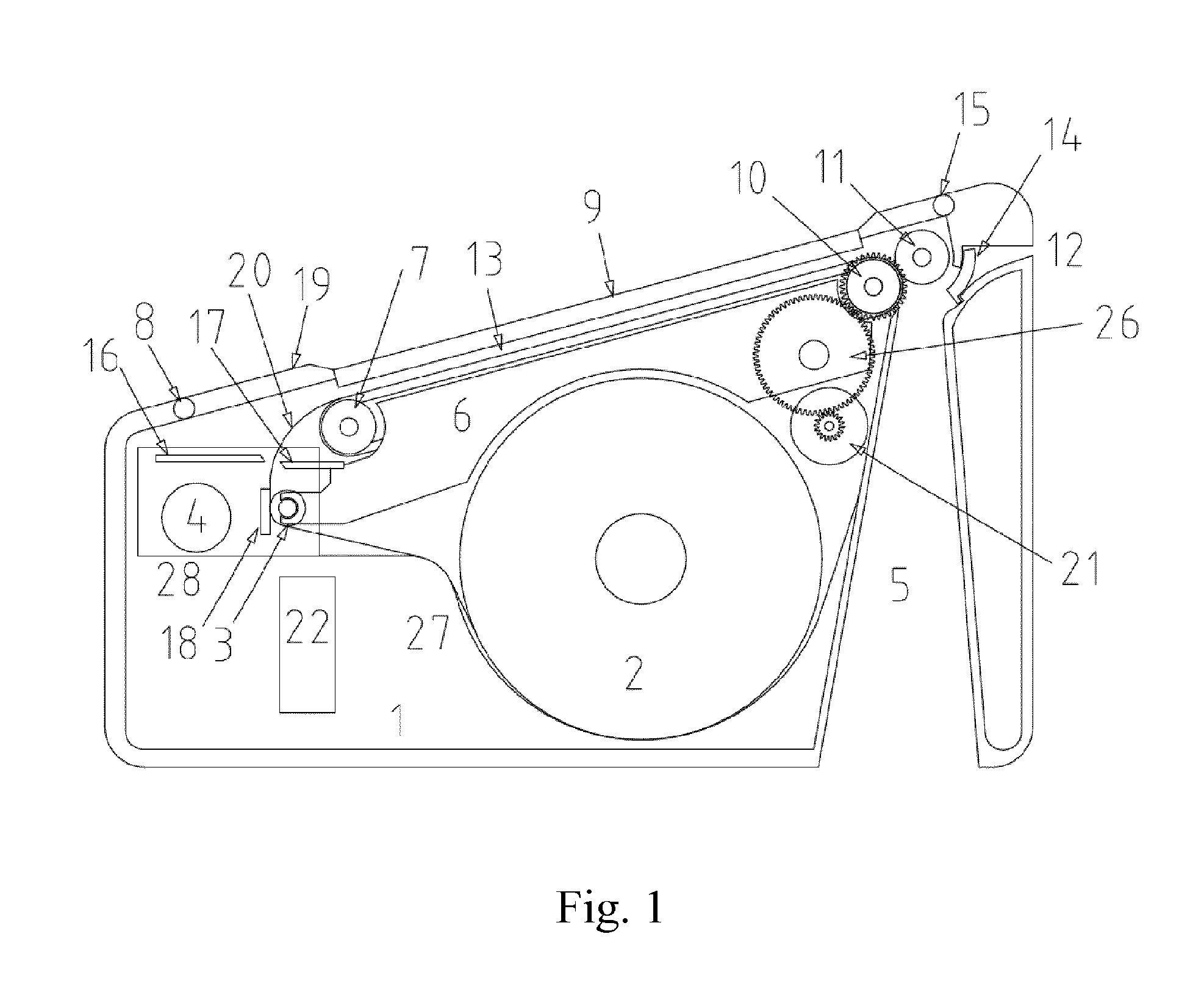
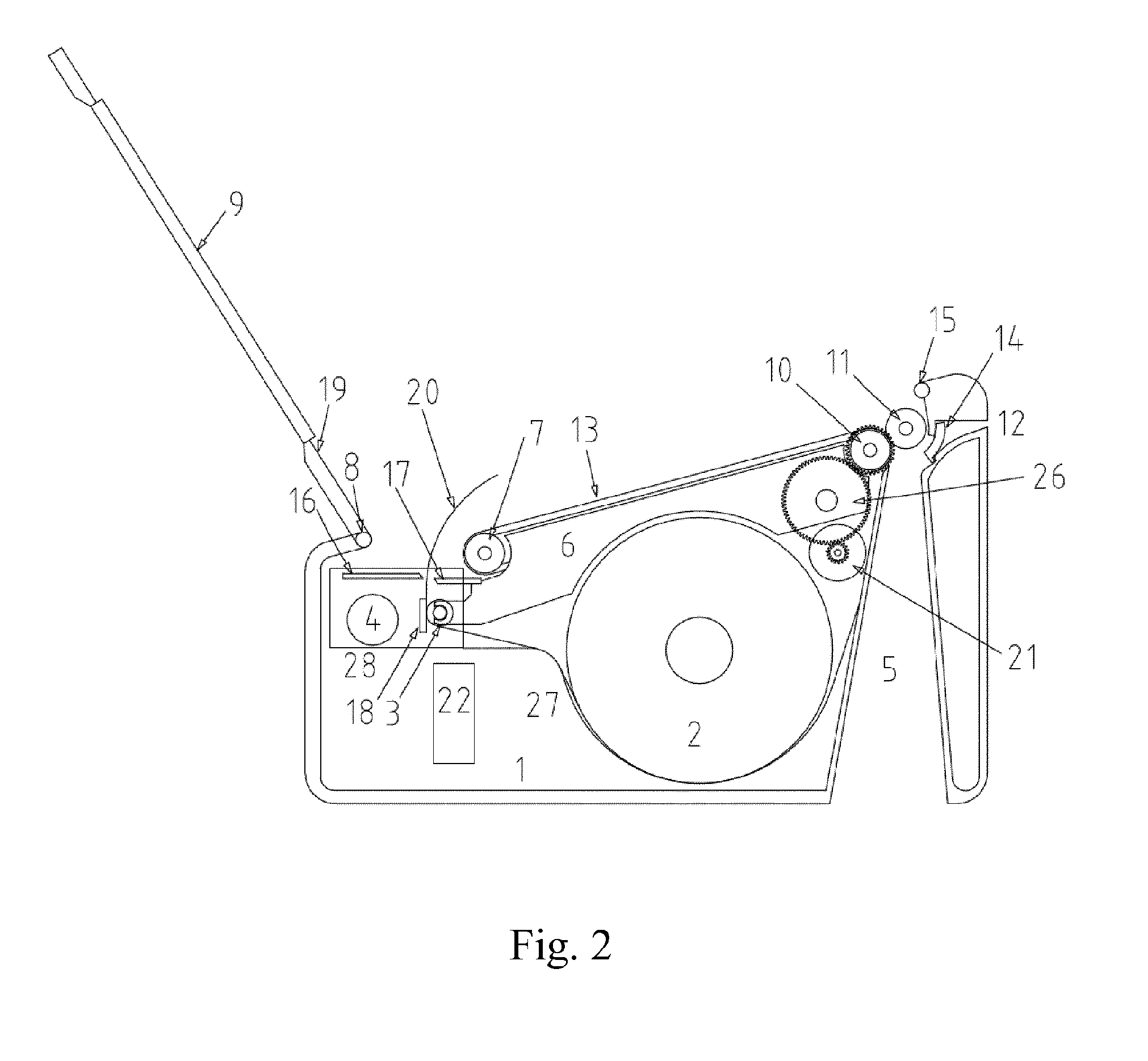
[0036]FIG. 1 shows a preferred embodiment of the thermal printing device for electronic voting apparatus according to the present invention. The thermal printing device comprises a casing 1 with paper reservoir 27 for receiving a paper roll 2, an openable external lid 19 with a transparent window 9 for observing of a printed part of the paper, a thermal printing unit 28, a paper transport unit 6 for transporting the paper, arranged below the transparent window 9, and a ballot discharge opening 5 of the casing provided after the paper transport unit 6. A cutting device comprising two blades 16 and 17 able to cooperate to cut the paper is arranged after the thermal printing unit 28 and before the paper transport unit 6.

[0037]The thermal printing unit 28 comprises a thermo-printing head 18, a driving rubber roller 3 for the paper and a driving motor 4.

[0038]The paper transport unit 6 comprises at least one paper transport belt 13 held between at least two pulleys 7 and 10 mounted on a ...


PUM


Abstract

A thermal printing device for electronic voting apparatus including a casing with paper reservoir for receiving a paper roll, an openable external lid with a transparent window for observing of a printed part of the paper, a thermal printing unit with a driving rubber roller for the paper, a cutting device with two blades, a paper transport unit for transporting the paper, arranged below the transparent window, and a ballot discharge opening of the casing provided after the paper transport unit. The rubber roller and one of the blades of the cutting device are integral with part of the paper transport unit that is openable in order to give access to the paper reservoir.

Description

CROSS-REFERENCE TO RELATED APPLICATION[0001]The present application is the US national phase of International Patent Application No. PCT / EP2014 / 053431, filed Feb. 21, 2014, which application claims priority to European 13157369.3, filed Mar. 1, 2013. The priority application, EP 13157369.3, is hereby incorporated by reference.TECHNICAL FIELD OF THE INVENTION[0002]The invention relates to a thermal printing device for electronic voting system.PRIOR ART[0003]Electronic voting apparatuses are used in different kinds of elections. In the process of voting using such electronic voting apparatus, the voter:[0004]first selects the candidate he / she intends to vote for;[0005]then the printer of the voting apparatus prints a coupon (ballot) corresponding to the voter's choice;[0006]the printed coupon is presented to the voter usually under a transparent glass; and[0007]after the voter's confirmation, the coupon is then cut and ejected into the ballot box.[0008]In the voting application, the p...

Claims


Application Information

Patent Timeline
Patent Type & Authority Patents(United States)
IPC IPC(8): B41J11/00G07C13/00B41J11/70
CPCG07C13/00B41J11/70B41J15/042
Inventor MONTAGUTELLI, DENIS
Owner APS TRADING OOD
Learn More