Ball transfer unit for cargo bay

a transfer unit and cargo technology, applied in the direction of conveyor parts, rollers, roller-ways, etc., can solve the problems of many prior designs that are prone to contamination, not uncommon for cargo holds in vehicles to be subject to periodic ingress, and many prior designs that suffer from common shortcomings. , to achieve the effect of preventing water ingress

Active Publication Date: 2016-01-19
KALITTA AIR
View PDF19 Cites 10 Cited by
  • Summary
  • Abstract
  • Description
  • Claims
  • Application Information

AI Technical Summary

Benefits of technology

[0007]According to the present invention, there is provided a ball transfer unit for use in association with installed trays in vehicle cargo bays. The ball transfer units are modular units that comprise a large or main roller ball element, a semi-spherical housing for holding that element, a plurality of smaller ball elements interposed between the housing and the main ball element and a unitary cover affixed to the housing for securing the various ball elements in relation to the housing and cover, whereby the large ball element protrudes partially through said cover and where the cover is designed to discourage the ingress of water and contaminants into the housing.
[0008]The cover is manufactured without seams, and includes a transitional elevated portion of sufficient height to prevent most ingress of water or contaminants. The housing and cover may be machined, rather than cast, from high strength steel stock, such as, for example, stainless steel, which imparts substantial strength to the unit, reduces deterioration resulting from elemental exposure and provides the necessary strength to support a significant distributed and undistributed loads.

Problems solved by technology

While prior systems may have certain functional and useful features, many of the prior system suffer from common shortcomings.
For example, it is not uncommon for cargo holds in vehicles to be subject to the periodic ingress of water, dirt or other contaminants.
As a result, many prior designs are prone to contamination and may act as receptacles for unwanted water.
As dirt, dust and other debris find their way into cargo holds, prior designs have a tendency to allow, or even facilitate, the entry of such contaminants into the ball transfer units.
At some point, oxidation of the internal components of ball transfer units may occur, and the collection and concentration of debris in the interior of the units may significantly increase the internal friction occurring within the units, which may render them inefficient and make it difficult for cargo to be easily moved over the ball transfer assemblies.
In addition, many prior devices have seams on their upper surfaces that may provide opportunities for cargo to get caught and immobilized during the loading and unloading processes of the cargo bay.
It is not uncommon for cast units to fracture under these loads, rendering the damaged ball transfer unit useless.

Method used


Image

  • Ball transfer unit for cargo bay
  • Ball transfer unit for cargo bay
  • Ball transfer unit for cargo bay

Examples


Embodiment Construction

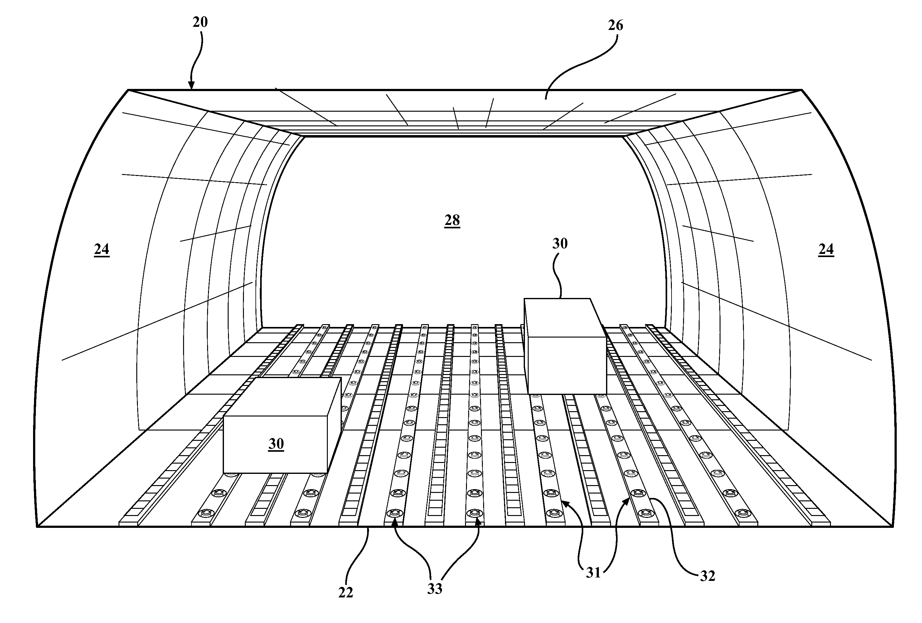
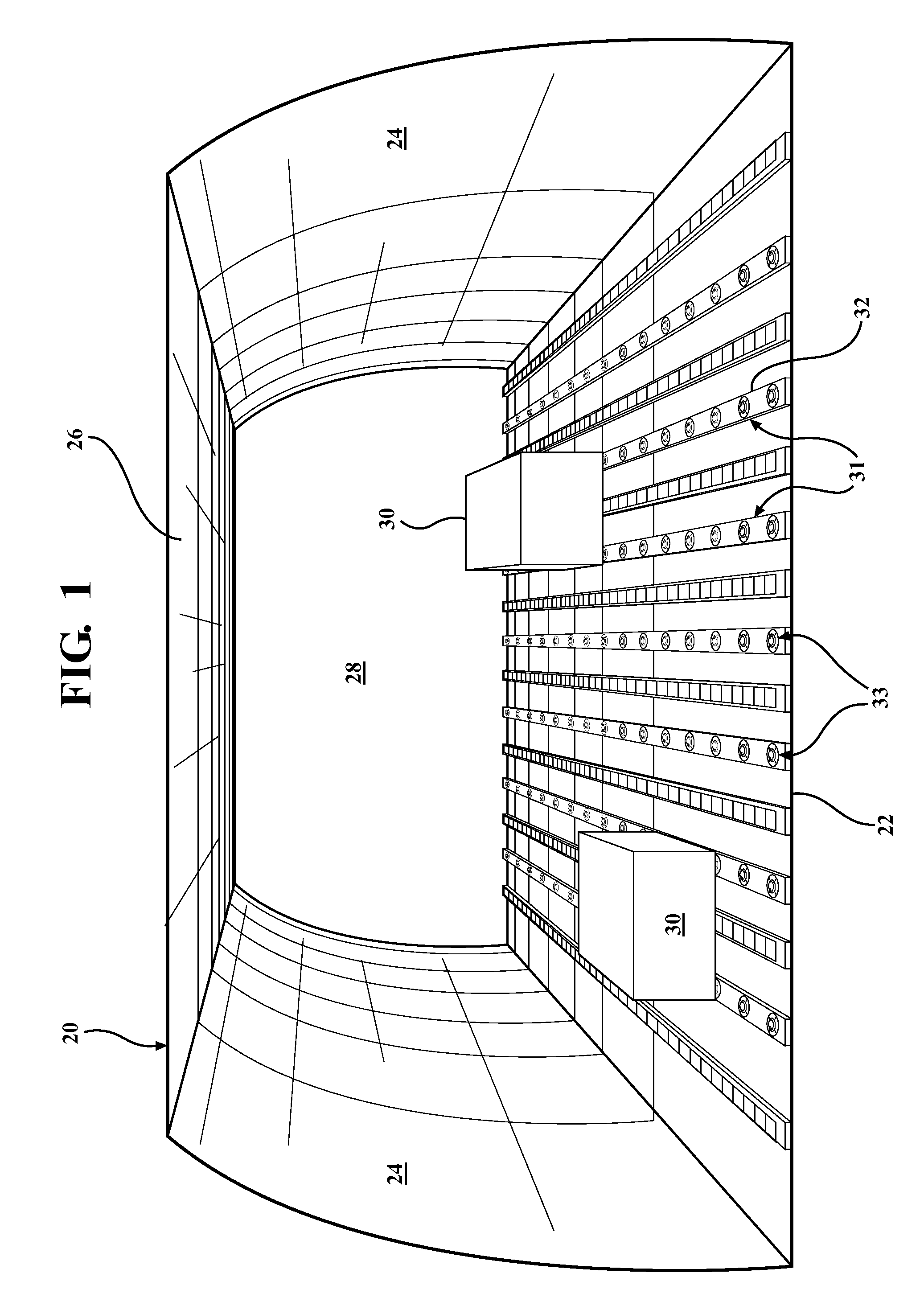
[0022]A typical cargo hold 20, such as may be found, for example, in an aircraft, is illustrated in FIG. 1. The cargo hold 20 may include a cargo hold floor 22, opposing cargo hold walls 24 and a cargo hold ceiling 26, which serve to define a generally confined compartment 28 in which a wide range of cargo 30 may be positioned, secured and transported. Attached to the cargo hold floor 22 are multiple elongated roller unit 31 that include a roller tray 32 configured to support a ball transfer unit 33. The roller unit 31 may also be mounted to the cargo hold walls 24. The number of roller units 31 disposed within the cargo hold 20 may depend, at least in part, upon the size of the cargo hold 20 and the configuration and weight of the cargo 30 to be distributed along the roller unit 31. The roller unit 31 may be permanently or semi-permanently mounted to the cargo hold floor 22.

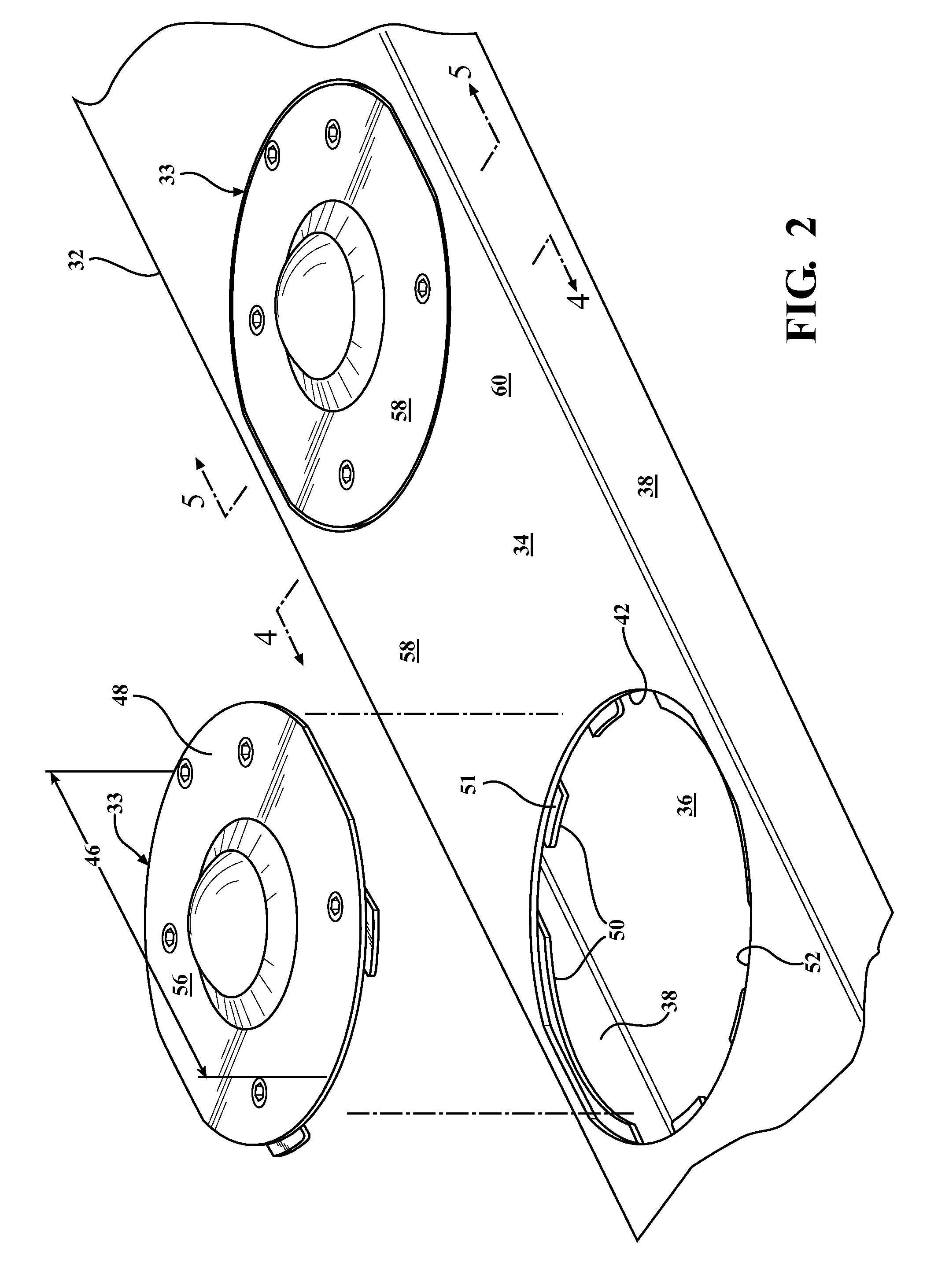
[0023]With reference to FIGS. 2-5, the roller tray 32 may be generally configured in the shape of a rectangul...


PUM


Abstract

A ball transfer unit for use in association with installed trays in vehicle cargo bays. Ball transfer unit is a modular unit that includes a larger main roller ball, a semi-spherical housing for holding the larger main roller ball, a plurality of smaller roller balls interposed between the housing and the main roller ball and a unitary cover affixed to the housing for securing the various ball elements in relation to the housing and cover. The large roller ball protrudes partially through the cover, and the cover is designed to discourage the ingress of water and contaminants from entering the housing.

Description

RELATED APPLICATIONS[0001]This application claims benefit of U.S. Provisional Application No. 61 / 807,532 filed on Apr. 2, 2013, which is incorporated by reference herein in its entirety.FIELD OF THE INVENTION[0002]The invention relates to a ball transfer unit configured to be mounted on a floor of a cargo hold.BACKGROUND OF THE INVENTION[0003]Various systems for movably supporting cargo on the floor of cargo holds, such as those found in aircraft, sea-going cargo ships and other cargo-carrying vehicles, have been previously proposed. Typically, such systems include a plurality of roller ball elements mounted on the floor of the cargo hold, thereby providing a low friction support surface over which cargo may be moved. In a typical cargo hold, the floor, and sometimes the walls, are provided with a plurality of elongated trays that are permanently or semi-permanently attached to the floor or other interior surface of the cargo hold. Each tray accommodates one or more ball transfer un...

Claims


Application Information

Patent Timeline
Patent Type & Authority Patents(United States)
IPC IPC(8): B65G39/00B65G39/02B65G13/00B65G39/10B65G39/12B64D9/00
CPCB65G39/025B64D9/00B65G39/12B64D2009/006
Inventor KALITTA, CONRADBREWER, STEVEN
Owner KALITTA AIR
Why Eureka
Try Eureka