Zoom lens and imaging apparatus

a zoom lens and imaging apparatus technology, applied in the field of zoom lenses and imaging apparatuses, can solve the problems of difficult to achieve weight reduction, increase the weight of the lens system, and difficulty in reducing magnification, so as to achieve rapid zoom movement, increase the load on the cam, and high sensitivity

Inactive Publication Date: 2016-01-19
FUJIFILM CORP
View PDF15 Cites 2 Cited by
  • Summary
  • Abstract
  • Description
  • Claims
  • Application Information

AI Technical Summary

Benefits of technology

[0106]It is more preferable for conditional formula (1-1) below to be satisfied to enhance the advantageous effects described above:
[0107]Each of FIGS. 6 through 10 is a graph showing the relationship between zoom ratios and the distances between the third-a lens group G3a and the third-b lens group G3b in each of the first through the fifth examples of configurations. Note that in the present embodiment, the focal length where the image formation magnification rates of the second lens group G2 and the third lens group G3 simultaneously become −1× is employed as a standard. The vertical axis in the graph shown in each of FIGS. 6 through 10 indicates G3d-G3db1 which is each value obtained by subtracting the distance G3db1 between the third-a lens group G3a and the third-b lens group G3b at the focal length where the image formation magnification rates of the second lens group G2 and the third lens group G3 simultaneously become −1× from the distance G3d between the third-a lens group G3a and the third-b lens group G3b. As shown in FIGS. 6 through 10, the distance between the third-a lens group G3a and the third-b lens group G3b is configured to be maximum in the zoom range from the wide angle end to the focal length where the image formation magnification rates of the second lens group G2 and the third lens group G3 simultaneously become −1× while changing magnification, in the first through the fifth examples of configurations (Examples 1 through 5).
[0108]In the zoom lens of the present embodiment, it is preferable for the distance between the second-a lens group G2a and the second-b lens group G2b to be minimum in the zoom range from the wide angle end to the focal length where the image formation magnification rates of the second lens group G2 and the third lens group G3 simultaneously become −1× while changing magnification and for conditional formula (2) to be satisfied:−0.012<(G2dmin−G2db1) / f2b<−0.002  (2), whereG2db1: the distance between the second-a lens group G2a and the second-b lens group G2b at a zooming position where the image formation magnification rates of the second lens group G2 and the third lens group G3 simultaneously become −1,G2dmin: the minimum value of the distance between the second-a lens group G2a and the second-b lens group G2b in the zoom range described above, andf2b: the focal length of the second-b lens group G2b.
[0109]In general, when trying to achieve high magnification, the amount of aberrations, particularly field curvature at the telephoto side will increase. When this aberration is corrected, correcting various aberration, particularly field curvature will be difficult in the zoom range from the wide angle end to the focal length where the image formation magnification rates of the second lens group G2 and the third lens group G3 simultaneously become −1×. The second lens group G2 is the only lens group having a negative refractive power among the lens groups which constitute the zoom lens of the present embodiment. Accordingly, the second lens group G2 has a strong refractive power and has high sensitivity with respect to field curvature. Configuring the distance between the second-a lens group G2a and the second-b lens group G2b to be minimum in the zoom range from the wide angle end to the focal length where the image formation magnification rates of the second lens group G2 and the third lens group G3 simultaneously become −1× while changing magnification enables satisfactory correction of the imaging plane in the zoom range described above.
[0110]Setting the value of (G2dmin-G2db1) / f2b to fall below the lower limit defined by conditional formula (2) will cause the amount of feeding out the second-b lens group G2b to increase. Thereby, a load on a cam will increase when changing magnification by a cam drive so that rapid zoom movement will be difficult. Further, various aberrations other than field curvature, particularly spherical aberration will become worse, which is unfavorable. Setting the value of (G2dmin-G2db1) / f2b to exceed the upper limit defined by conditional formula (2) will cause the amount of feeding out the second-b lens group G2b to decrease. Thereby, the effect of correcting field curvature will deteriorate, which is unfavorable.
[0111]It is more preferable for conditional expression (2-1) below to be satisfied in order to enhance the advantageous effects described above:−0.010<(G2dmin−G2db1) / f2b<−0.004  (2-1).

Problems solved by technology

Accordingly, increasing the diameter of the first lens group further will make it difficult to achieve reduction in weight.
In contrast, making the angle of view of the lens wider and the configuration of the most-image-side lens group complicated to achieve a wider angle of view will increase the weight of the lens system.
Therefore, increasing magnification is difficult to achieve reduction in weight.

Method used


Image

  • Zoom lens and imaging apparatus
  • Zoom lens and imaging apparatus
  • Zoom lens and imaging apparatus

Examples


example 1

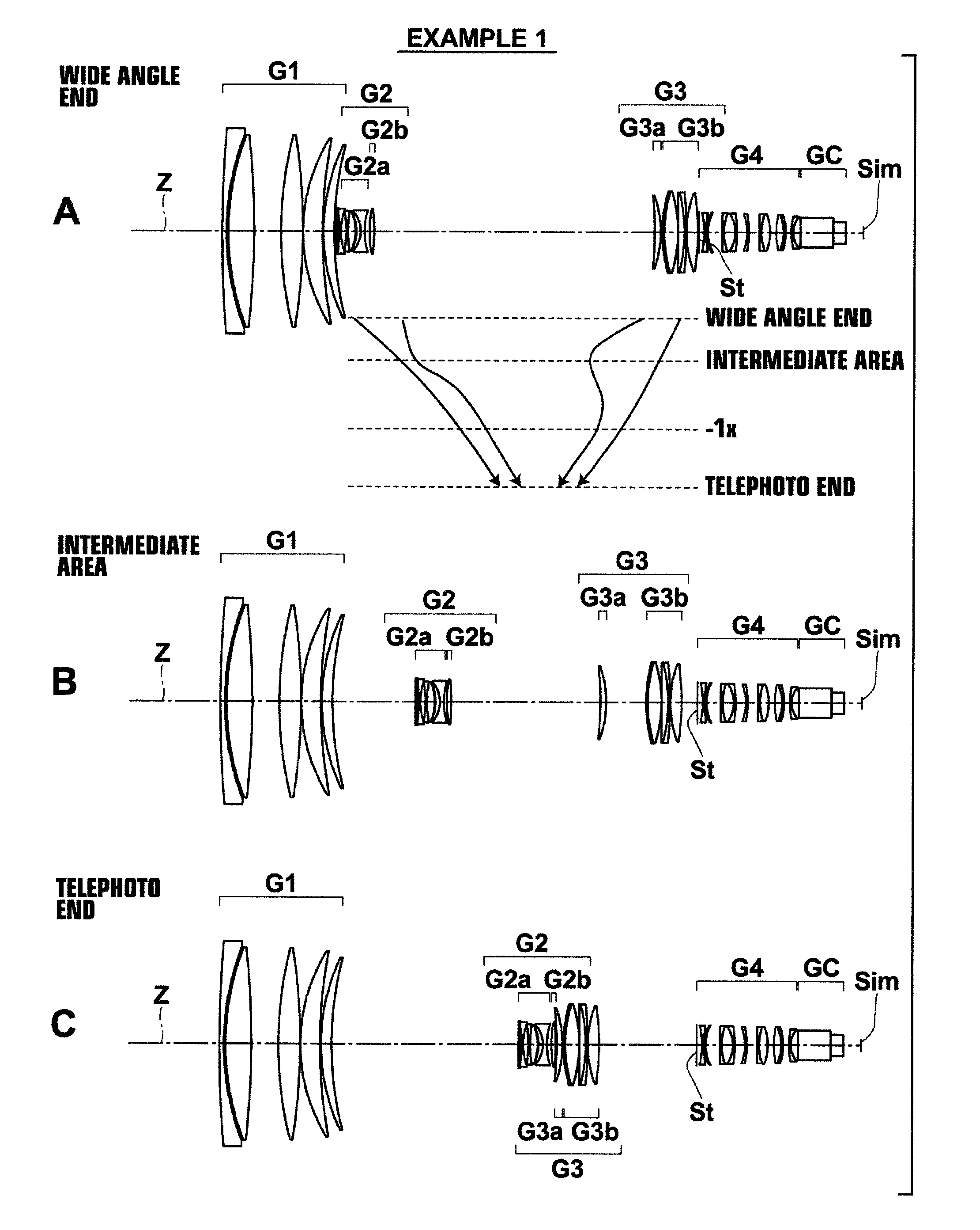
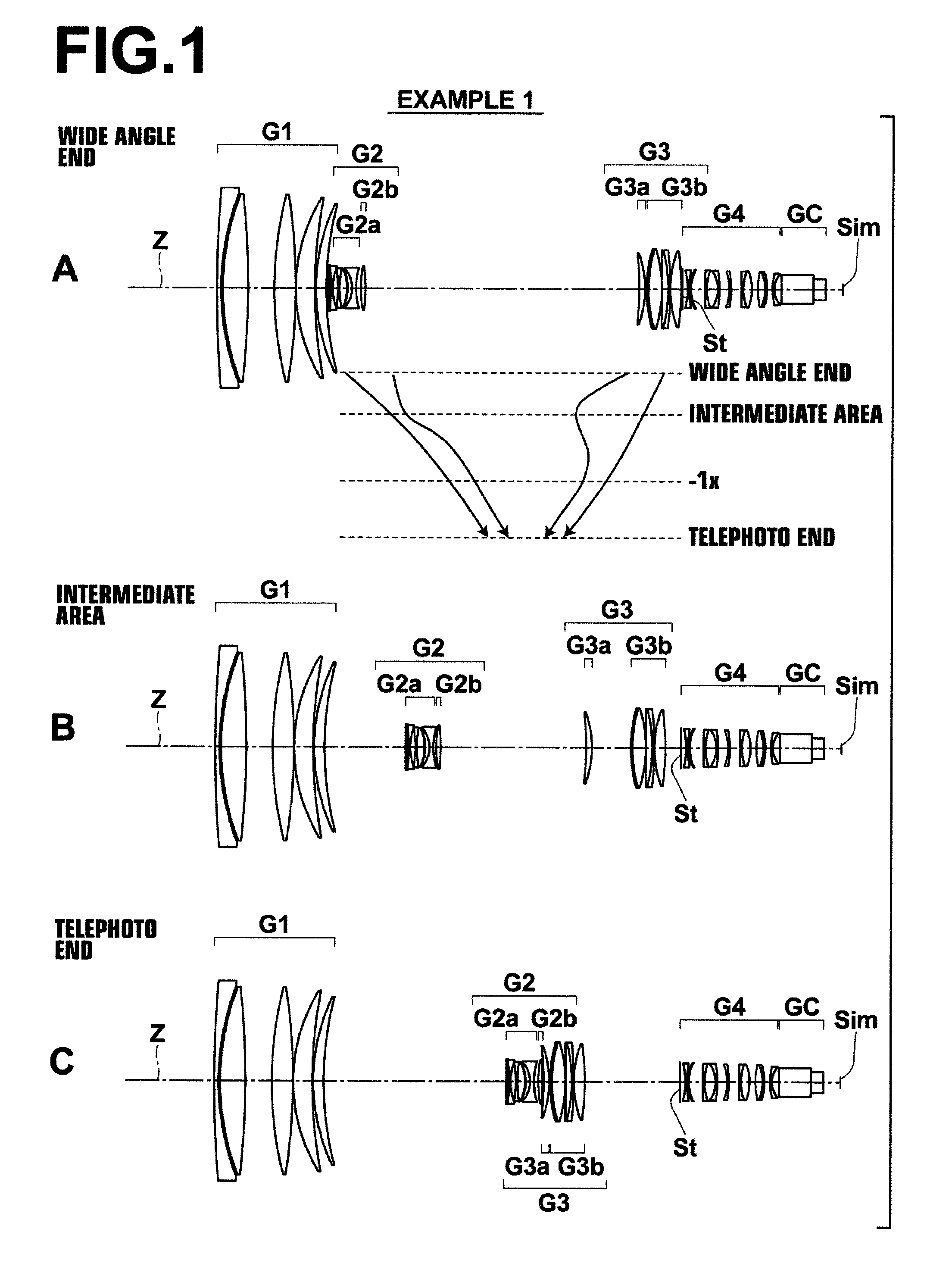
[0125]The cross sectional view of the lens of Example 1 is shown in FIG. 1. Detailed configurations thereof are shown in FIGS. 16 through 18. FIG. 16 shows detailed configurations of the first lens group G1 and the second lens group G2, FIG. 17 shows a detailed configuration of the third lens group G3, and FIG. 18 shows detailed descriptions from the fourth lens group G4 to the image formation surface Sim.

[0126]In Example 1, the first lens group G1 is of a five-lens configuration including lenses L1 through L5, the second-a lens group G2a which constitutes the second lens group G2 is of a six-lens configuration including lenses L21 through L26, the second-b lens group G2b is of a one-lens configuration including a lens L27, a third-a lens group G3a which constitutes the third lens group G3 is of a one-lens configuration including a lens L31, a third-b lens group G3b is of a five-lens configuration including lenses L32 through L36, and the fourth lens group is of a twelve-lens config...

example 2

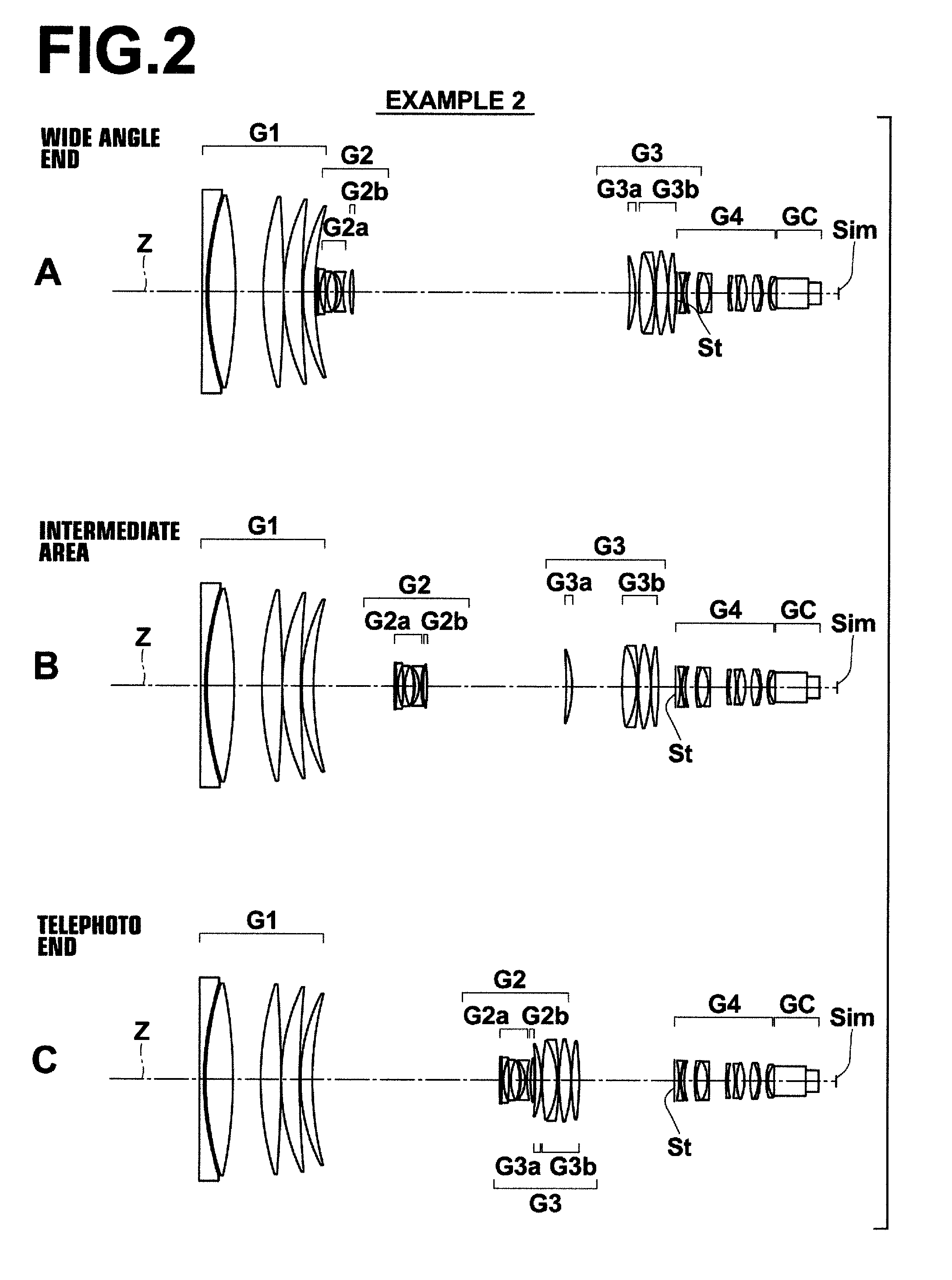
[0137]The cross sectional view of lenses in Example 2 is shown in FIG. 2, and detailed configurations thereof are shown in FIGS. 19 through 21. FIG. 19 shows the detailed configuration of the first lens group G1 and the second lens group G2, FIG. 20 shows the detailed configuration of the third lens group G3, and FIG. 21 shows the detailed configuration from the fourth lens group G4 to the image formation surface Sim.

[0138]In Example 2, the first lens group G1 is of a five-lens configuration including lenses L1 through L5, the second-a lens group G2a which constitutes the second lens group G2 is of a six-lens configuration including L21 through L26, the second-b lens group G2b is of a one-lens configuration including a lens L27, the third-a lens group G3a which constitutes the third lens group G3 is of a one-lens configuration including a lens L31, the third-b lens group G3b is of a four-lens configuration including lenses L32 through L35, and the fourth lens group is of a twelve-le...

example 3

[0143]The cross sectional view of lenses in Example 3 is shown in FIG. 3, and detailed configurations thereof are shown in FIGS. 22 through 24. FIG. 22 shows the detailed configuration of the first lens group G1 and the second lens group G2, FIG. 23 shows the detailed configuration of the third lens group G3, and FIG. 24 shows the detailed configuration from the fourth lens group G4 to the image formation surface Sim.

[0144]In Example 3, the first lens group G1 is of a five-lens configuration including lenses L1 through L5, the second-a lens group G2a which constitutes the second lens group G2 is of a six-lens configuration including L21 through L26, the second-b lens group G2b is of a one-lens configuration including a lens L27, the third-a lens group G3a which constitutes the third lens group G3 is of a one-lens configuration including a lens L31, the third-b lens group G3b is of a four-lens configuration including lenses L32 through L35, and the fourth lens group G4 is of a thirte...


PUM


Abstract

The zoom lens substantially consists of a positive first lens group which is fixed while changing magnification, a negative second lens group which moves while changing magnification, a positive third lens group which moves while changing magnification, and a positive fourth lens group which is fixed while changing magnification in this order from the object side. The image formation magnification rates of the second lens group and the third lens group simultaneously pass a −1× point while changing magnification from the wide angle to the telephoto. The second lens group substantially consists of a negative second-a lens group and a positive second-b lens group which independently move while changing magnification in this order from the object side, and the third lens group substantially consists of a positive third-a lens group and a positive third-b lens group which independently move while changing magnification in this order from the object side.

Description

CROSS-REFERENCE TO RELATED APPLICATIONS[0001]This application is a Continuation of PCT International Application No. PCT / JP2013 / 003333 filed on May 27, 2013, which claims priority under 35 U.S.C. §119(a) to Japanese Patent Application No. 2012-132859 filed on Jun. 12, 2012. Each of the above application(s) is hereby expressly incorporated by reference, in its entirety, into the present application.BACKGROUND OF THE INVENTION[0002]1. Technical Field[0003]The present invention relates to a zoom lens and an imaging apparatus, and particularly to a zoom lens having a high magnification ratio suitable for mounting onto TV cameras, video cameras, and the like and an imaging apparatus including this zoom lens.[0004]2. Description of the Related Art[0005]In recent years, needs for the zoom lenses which are intended to be mounted onto a TV camera, a video camera, and the like to have higher magnification ratios, wider angles of view, lighter weights, and higher performance throughout the ent...

Claims


Application Information

Patent Timeline
Patent Type & Authority Patents(United States)
IPC IPC(8): G02B15/14G02B15/173G02B13/18
CPCG02B15/173G02B13/18G02B15/144113
Inventor AOI, TOSHIHIROIKEDA, SHINKICHI
Owner FUJIFILM CORP
Why Eureka
Try Eureka