Three-dimensional image display

a three-dimensional image and display technology, applied in lighting devices, lighting and heating devices, instruments, etc., can solve the problem of providing the illusion of a three-dimensional display, and achieve the effect of less occlusion and minimization of occlusion

Active Publication Date: 2016-01-19
SOFTRONICS
View PDF5 Cites 3 Cited by
  • Summary
  • Abstract
  • Description
  • Claims
  • Application Information

AI Technical Summary

Benefits of technology

[0008]In an embodiment, the directional pixels are interlaced with spaces. Interlacing spaces between each directional pixel permits each directional pixel to display light in all three dimensions and minimizes occlusion from a directional pixel that is in front of another directional pixel. The ratio of interlacing spaces to directional pixels can be any value, but the greater the ratio of spaces to directional pixels, the less occlusion there is.

Problems solved by technology

These techniques are appropriate for computer games and CAD application software but only provide the illusion of a 3D display because the scene is shown on a 2D display.
Again, this technology only provides the illusion of a 3D display because the scene is still shown on a 2D display.

Method used


Image

  • Three-dimensional image display
  • Three-dimensional image display
  • Three-dimensional image display

Examples


Embodiment Construction

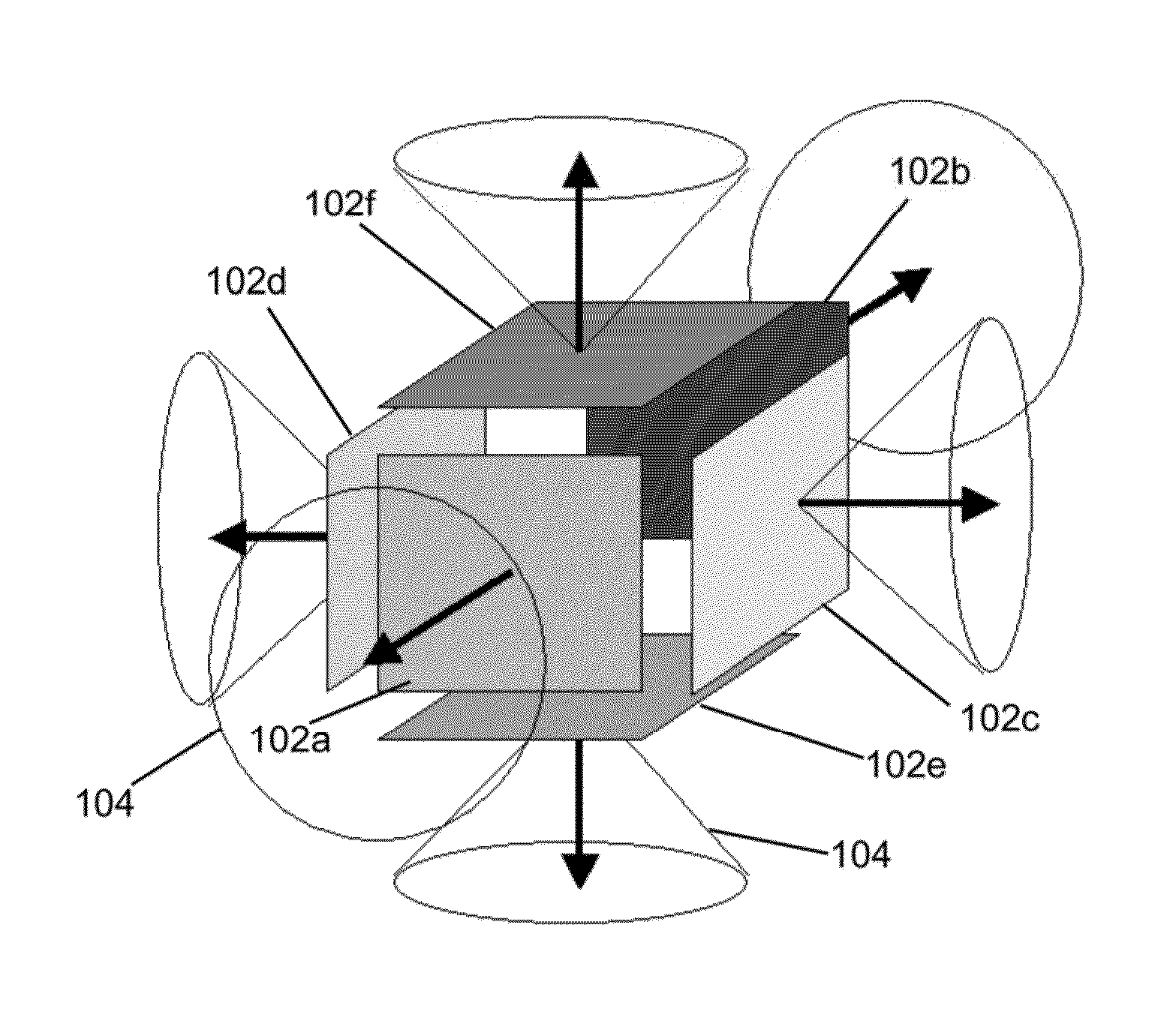
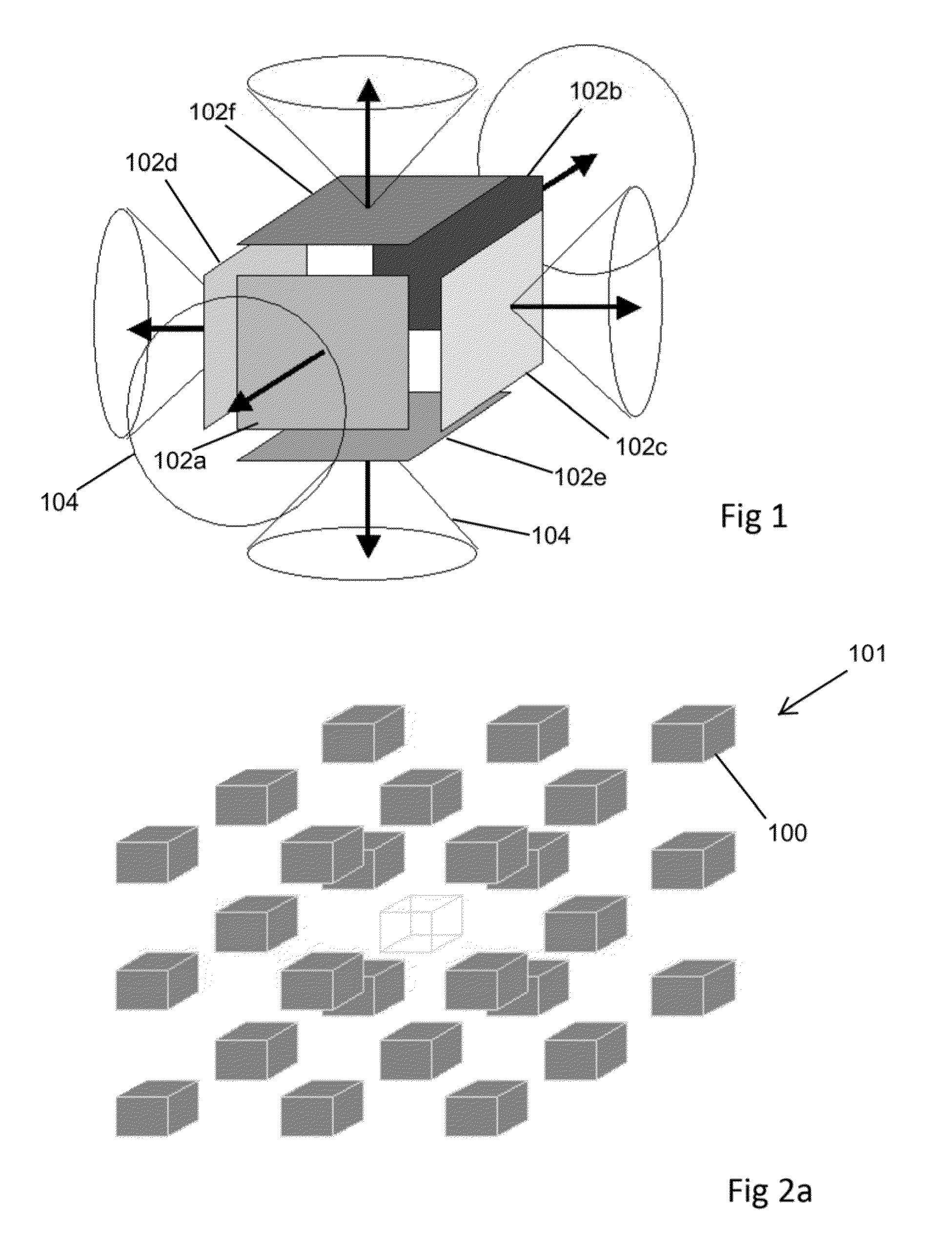
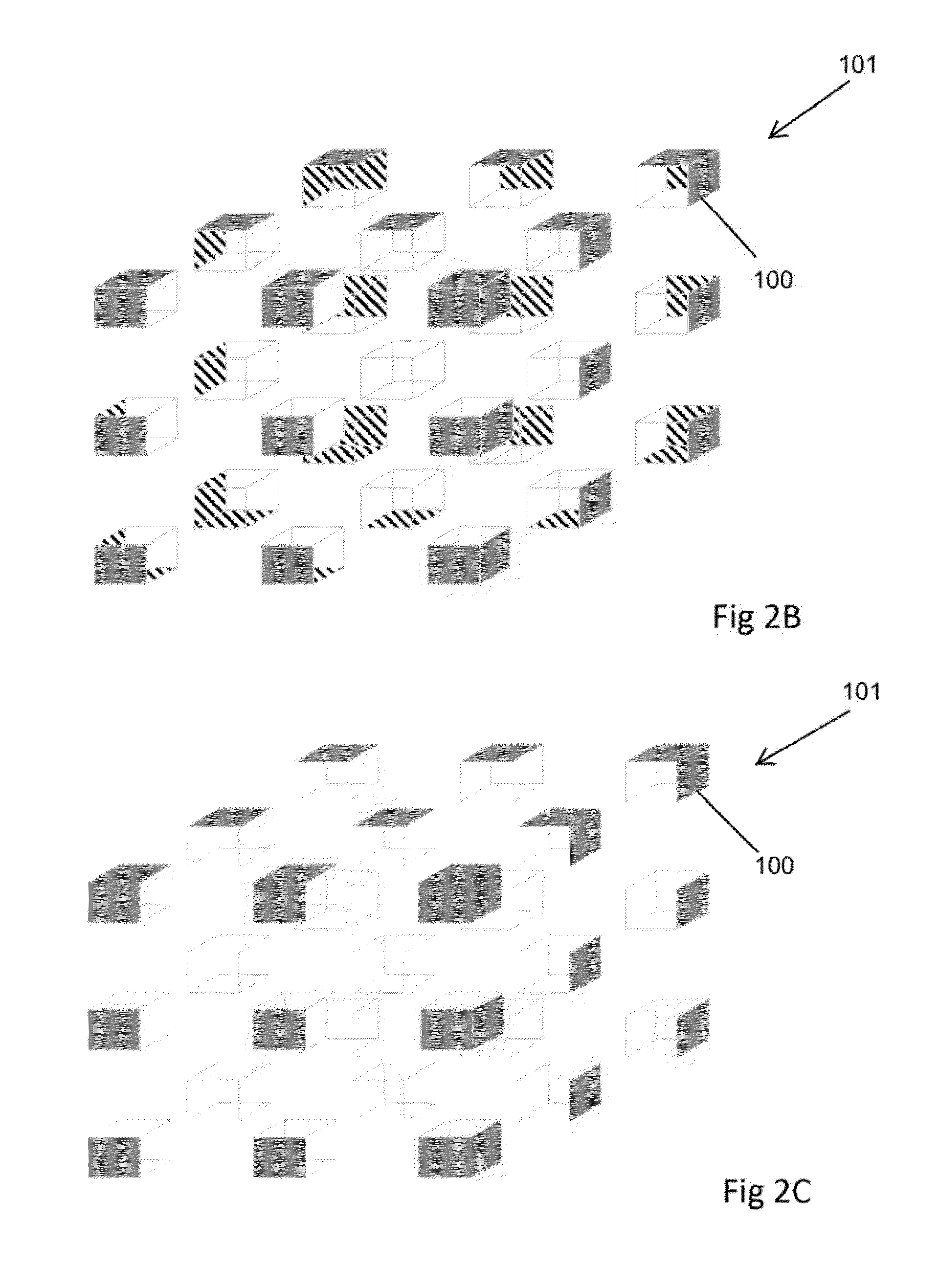
[0040]The present invention is directed toward a true three-dimensional (3D) display for displaying a true 3D image of an object or scene.

[0041]This disclosure uses the term “observer” and “reader”. An observer represents a person who can move 360° around (both in elevation and azimuth) the object or scene, while the reader represents the person reading this disclosure and viewing the figures from the illustrative perspective.

[0042]A scene, from the perspective of the observer, is composed of surfaces, which can be a field of incrementally small contiguous sub-surfaces that each corresponds to the observer's angular position. As an observer moves 360° around (both in elevation and azimuth) the object or scene, the sequence of surfaces varies in a potentially complex manner. The observer will always see the topmost surface with respect to the observer's current position for each angular increment of the observer's field of view. There can be nothing obstructing the observer's view of...


PUM

PropertyMeasurementUnit
luminanceaaaaaaaaaa
volumeaaaaaaaaaa
angleaaaaaaaaaa

Abstract

An image display to provide a realistic 3D stereoscopic image of a desired scene. The display device is comprised of directional pixels. Each directional pixel has a plurality of facets having a constrained viewing angle. Each facet has a point source of light that emits light with a controllable luminescence and hue. In this regard, each facet of the directional pixel has a constrained viewing angle and independent luminance and hue.

Description

[0001]This application is a continuation of patent application Ser. No. 13 / 749,965 filed Jan. 25, 2013 which application claims priority to U.S. Provisional Patent Application 61 / 592,360 filed Jan. 30, 2012, both of which applications are incorporated by reference herein.FIELD OF THE INVENTION[0002]The present invention relates generally to image display devices, and more particularly to three-dimensional image display devices.BACKGROUND OF THE INVENTION[0003]Creating the illusion of three-dimensional (3D) images on a display device or projection screen has been attempted for many years. In the 1950s, 3D movies were popular with polarized glasses worn to separate images for the left and right eye to provide for a stereoscopic view of the movie. Another area in which 3D imagery has been attempted is on raster scan displays. Generally, when the term 3D is used in regard to computer graphics, the term is referring to planar generated 3D images that are created using geometric perspecti...

Claims


Application Information

Patent Timeline
Patent Type & Authority Patents(United States)
IPC IPC(8): G02B26/00F21V14/02G02F1/01G02B27/22H04N13/393
CPCG02B27/22F21V14/02G02F1/01H04N13/393G02B30/27G02B30/50G02B30/54G02F1/0136
Inventor STERNOWSKI, ROBERT, H.
Owner SOFTRONICS
Why Eureka
Try Eureka