Connector

a technology of connecting rods and connectors, applied in the direction of connection, connection, basic electric elements, etc., can solve the problems of difficult to lower the profile and more highly integrate electrodes, and achieve the effects of more integrated, easy and reliable connection, and easy manufacturing

Active Publication Date: 2016-01-19
MOLEX INC
View PDF4 Cites 2 Cited by
  • Summary
  • Abstract
  • Description
  • Claims
  • Application Information

AI Technical Summary

Benefits of technology

[0008]In a typical conventional connector, the comb tooth guides 822 on the cover member 821 are inserted into and engage with the gaps 852 between exposed terminals 851 in the opening 812. Consequently, the height dimension of the housing 811 cannot be reduced, and the pitch between terminals 851 cannot be narrowed. This makes it difficult to lower the profile and more highly integrate electrodes as devices get smaller and more integrated.
[0009]It is an object of the Present Disclosure to solve the aforementioned problems by providing a reliable sheet connector in which protrusions are formed in the wiring lines connected to the conductive trace connecting portions of a flat cable, so that the flat cable can be connected more easily and reliably, can be manufactured more easily, and can be made more reliable even while making the configuration of the flat connector simpler, more integrated, more compact, and lower in profile.
[0015]In the connector of the Present Disclosure, protrusions are formed in the wiring lines connected to the conductive trace connecting portions of a flat cable. In this way, the flat cable can be connected more easily and reliably, can be manufactured more easily, and can be made more reliable even while making the configuration of the flat connector simpler, more integrated, more compact, and lower in profile.

Problems solved by technology

This makes it difficult to lower the profile and more highly integrate electrodes as devices get smaller and more integrated.

Method used


Image

  • Connector
  • Connector
  • Connector

Examples


Embodiment Construction

[0028]While the Present Disclosure may be susceptible to embodiment in different forms, there is shown in the Figures, and will be described herein in detail, with the understanding that the Present Disclosure is to be considered an exemplification of the principles of the Present Disclosure, and is not intended to limit the Present Disclosure to that as illustrated.

[0029]In the Present Disclosure, directional representations—i.e., up, down, left, right, front, rear and the like, used for explaining the structure and movement of the various elements of the Present Disclosure, are relative. These representations are appropriate when the elements are in the position shown in the Figures. If the description of the position of the elements changes, however, it is assumed that these representations are to be changed accordingly.

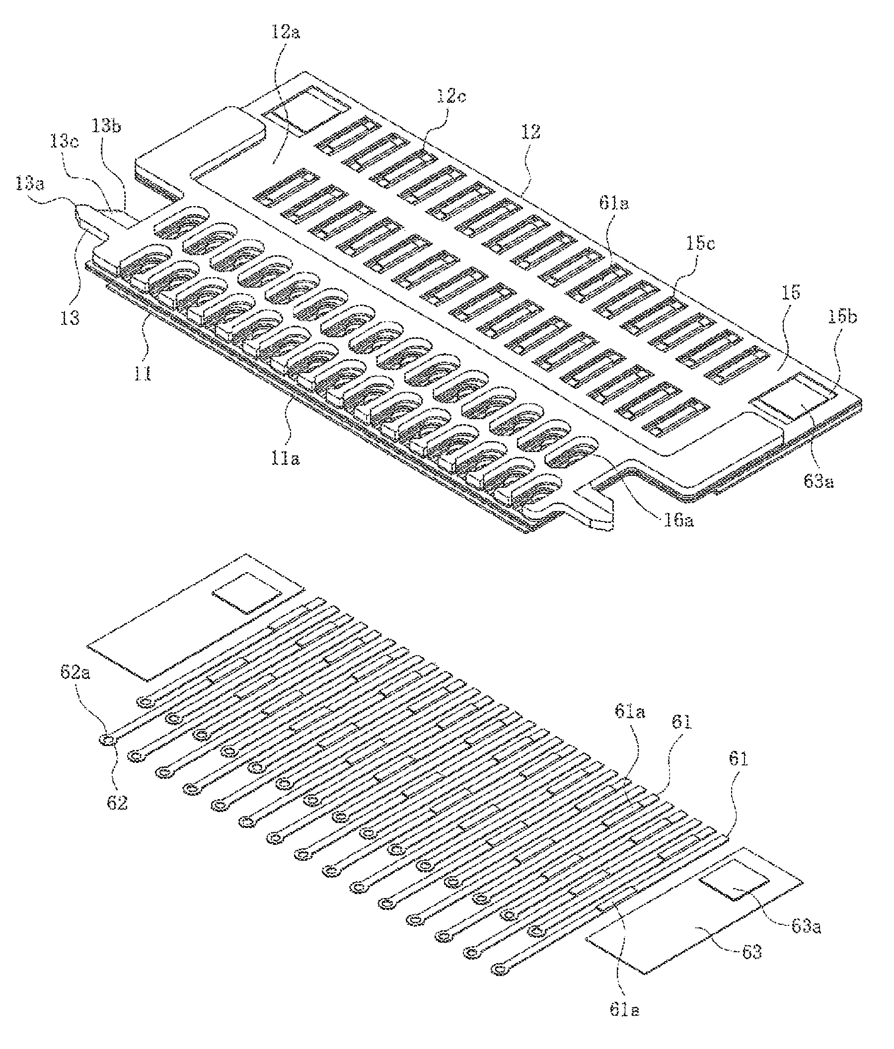
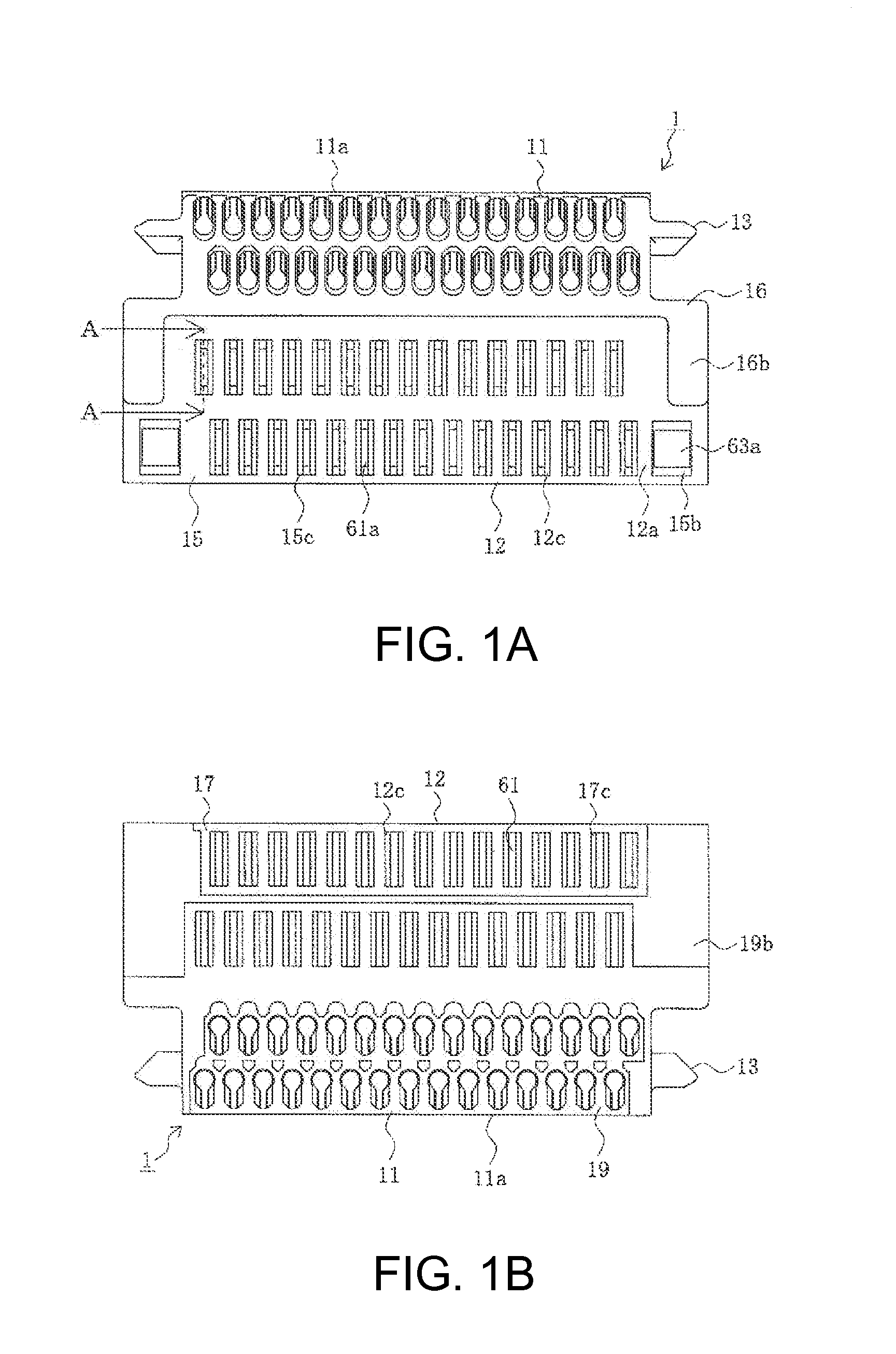
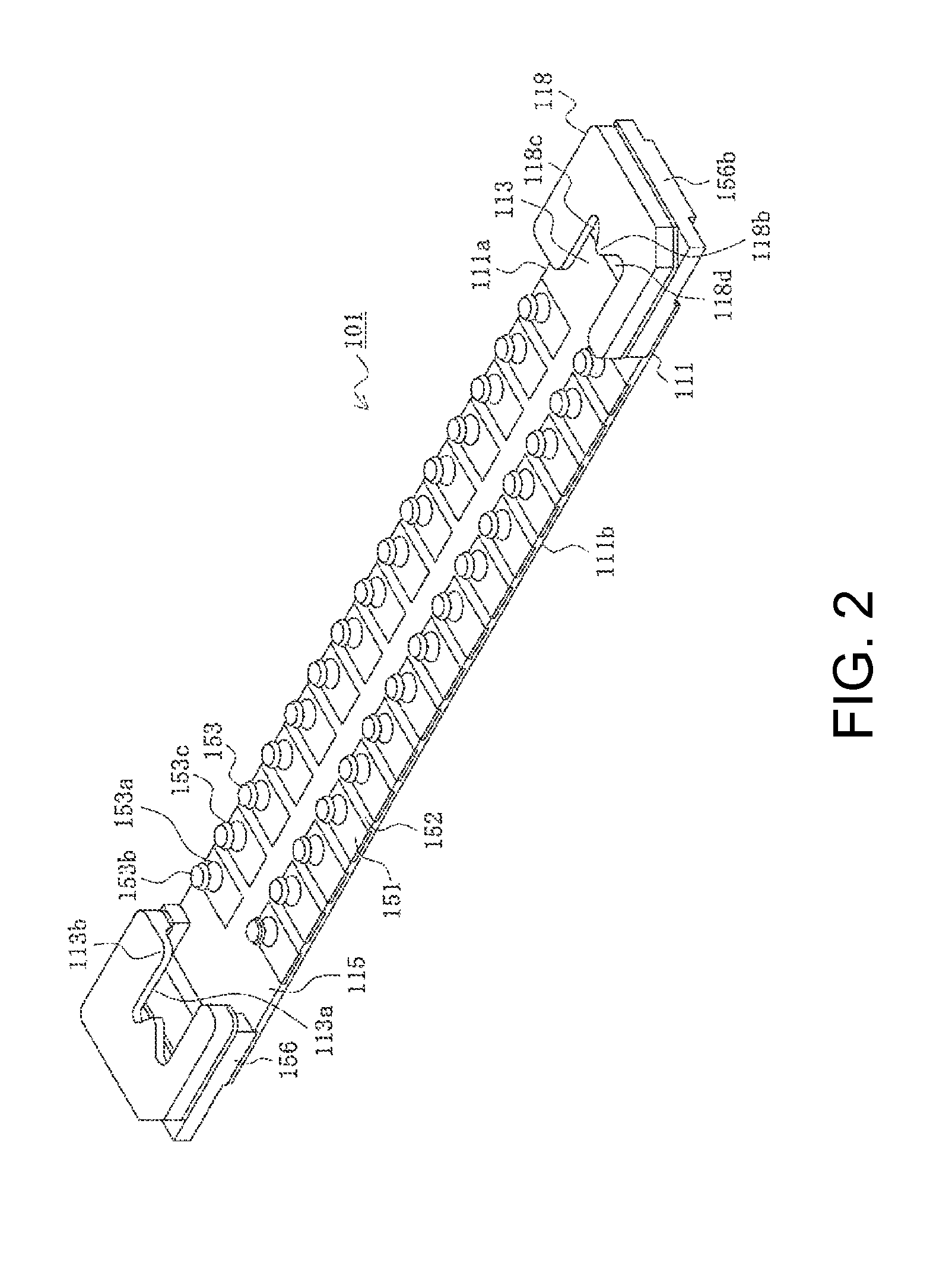
[0030]Referring to the Figures, 101 is the second connector among the connectors of the Present Disclosure and is a male connector. This connector is mounted on a...


PUM


Abstract

A connector is disclosed having a flat cable connecting portion connected to a flat cable and a flat mating portion mated with another connector. The connector comprises a plurality of terminals arranged on the mating portion for establishing contact with terminals on the other connector, a conductive connecting portion exposed on the cable connecting portion and connected to conductive trace connecting portions on the flat cable, and a plurality of wiring lines extending from the mating portion to the cable connecting portion, each one electrically connecting a terminal to the corresponding conductive trace connecting portion. The conductive connecting portion has a protrusion formed on the wiring lines. The upper surface of the protrusion is substantially the same height as one outer surface of the cable connecting portion.

Description

REFERENCE TO RELATED APPLICATIONS[0001]The Present Disclosure claims priority to prior-filed Japanese Patent Application No. 2013-102836, entitled “Connector,” and filed with the Japanese Patent Office on 15 May 2013, the content of which is fully incorporated in its entirety herein.BACKGROUND OF THE PRESENT DISCLOSURE[0002]The Present Disclosure relates, generally, to a connector.[0003]Electronic devices typically use connectors to connect components mounted on a printed circuit board to a flat cable such as a flexible printed circuit (FPC). An example is disclosed in Japanese Patent Application No. 1994-302961, the content of which is fully incorporated in its entirety herein.[0004]FIG. 11 is an exploded view of a typical conventional connector. In this drawing, 901 is a flexible circuit board including a plurality of conductors 961 formed by patterning copper foil formed on one surface of a resin sheet 915. The upper surfaces of the conductors 961 are covered with resin film 916....

Claims


Application Information

Patent Timeline
Patent Type & Authority Patents(United States)
IPC IPC(8): H01R12/78
CPCH01R12/78
Inventor SAGAYAMA, AKIRAIDA, AYAKOMIZUMURA, AKINORI
Owner MOLEX INC
Why Eureka
Try Eureka