Method and analysis system for eye examinations

a technology of ophthalmological analysis and eye examination, applied in the field of eye examination, can solve the problems of falsification of measurement, inability to obtain image record directly, and inability to measure eye length with comparable accuracy, and achieve the effect of high resolution of eye region

Active Publication Date: 2016-01-26
OCULUS OPTIKGERATE GMBH
View PDF4 Cites 15 Cited by
  • Summary
  • Abstract
  • Description
  • Claims
  • Application Information

AI Technical Summary

Benefits of technology

[0012]The present invention is therefore based on the task of proposing a method and an apparatus for measuring an eye, using which an image recording with a particularly high resolution of a region of the eye is made possible, wherein measurement errors which are conditioned by a movement of the eye during a measurement time interval are to be avoided.

Problems solved by technology

Thus, a measurement of an eye length having a comparable accuracy is not possible using a Scheimpflug system.
With the known OCT methods, it is disadvantageous that an image record cannot directly be obtained, i.e. that a corresponding period of time is required for scanning the eye section to be recorded by means of the measurement beam.
If a depth scan is to be procured, it is moreover required to adapt the reference arm with the corresponding expenditure of time.
Thus, eye movements in the time interval of the image recording using the optical coherence interferometer can lead to a falsification of the measurement results.
The movement of the eye consequently causes a change in the curvature of the corneal surface relative to the measurement beam and might cause a change in an index of refraction in the examination region of the eye.
In particular due to the change in the curvature of the cornea, another measurement error results since the measurement beam is diverted in a deviating way, for example at the corneal surface, due to the movement of the eye and the change in the curvature which is caused thereby.
Although movements of the eye can be identified by an offset of a received signal, this does not make a correction of a measurement error possible which results from a change in the curvature.
When recording an image of an eye section using a Scheimpflug system, the problem of measurement errors as a consequence of eye movements occurs only rarely, since the entire sectional image, in contrast to a scanned image, is recorded substantially simultaneously, since an exposure time of a camera chip is comparatively short.

Method used


Image

  • Method and analysis system for eye examinations
  • Method and analysis system for eye examinations
  • Method and analysis system for eye examinations

Examples


Embodiment Construction

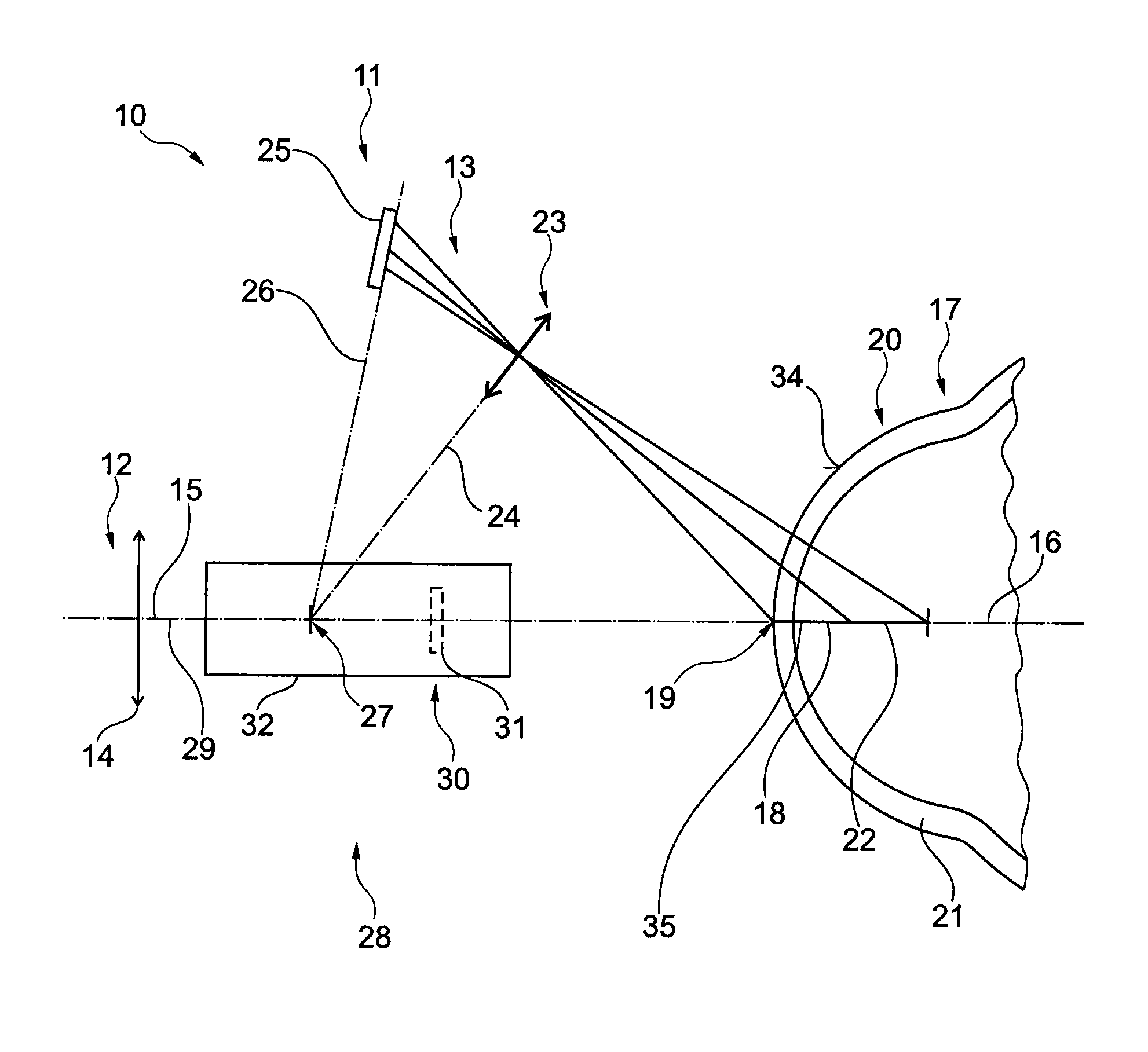
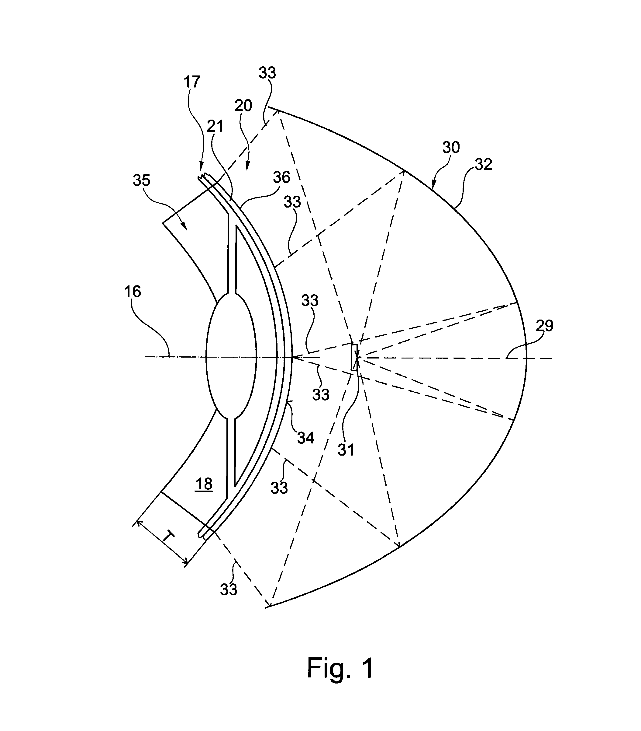
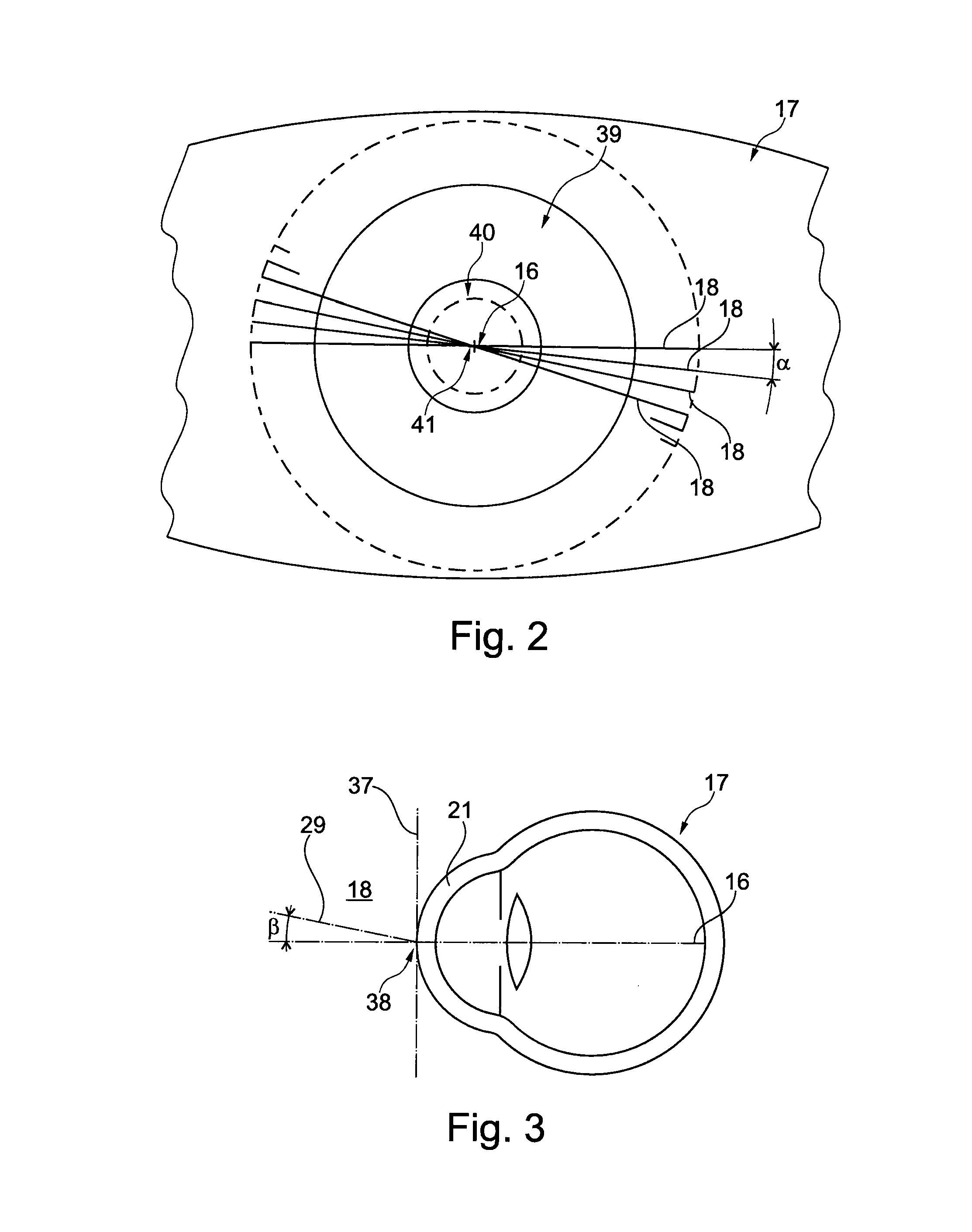
[0041]The basic structure of an ophthalmological analysis system 10 can be taken from FIGS. 4 and 5. A first analysis system 11, which is partially illustrated here, of the ophthalmological analysis system 10 is formed from a projection device 12 and from a monitoring device 13. As regards the projection device 12, only an objective lens 14 is schematically indicated here, through which objective lens a beam path 15 of a slit illumination, which is not illustrated in more detail here, is projected onto the eye 17 along a visual axis 16 of an eye 17. In FIGS. 4 and 5, the beam path 15 of the slit illumination runs in a recording plane 18, such that the slit illumination or the recording plane 18 runs horizontally and orthogonally relative to a viewing plane of FIG. 4 or parallel to a viewing plane of FIG. 5. The beam path 15, in the region of an apex 19 of the eye 17, enters a front eye section 20 having a cornea 21 of the eye 17, which cornea is schematically illustrated here, and p...


PUM


Abstract

An ophthalmological analysis system for examining an eye, in particular in the region of a front eye section of an eye includes first and second analysis systems obtaining sectional images of the eye. The first analysis system includes a projection device and a monitoring device arranged relative to each other according to the Scheimpflug rule. The second analysis system is an optical coherence interferometer. A processing device processes a first image data set obtained by the first analysis system and a second image data set obtained by the second analysis system to supplement the first image data set, at least partially, with data of the second image data set.

Description

CROSS-REFERENCE TO RELATED APPLICATIONS[0001]This application claims priority to German Patent Application No. 10 2013 207 987.7 filed on Apr. 30, 2013, which is fully incorporated herein by reference.STATEMENT REGARDING FEDERALLY SPONSORED RESEARCH OR DEVELOPMENT[0002]Not applicable.FIELD OF THE INVENTION[0003]The invention relates to a method and to an ophthalmological analysis system for examining an eye, in particular in the region of a front eye section of an eye, wherein the ophthalmological analysis system comprises a first analysis system for obtaining sectional images of the eye and a second analysis system, wherein the first analysis system is formed from a projection device and from a monitoring device, which are arranged relative to each other according to the Scheimpflug rule, wherein the second analysis system serves for obtaining sectional images of the eye, wherein the second analysis system is formed from an optical coherence interferometer, and wherein the ophthalm...

Claims


Application Information

Patent Timeline
Patent Type & Authority Patents(United States)
IPC IPC(8): A61B3/10A61B3/00A61B3/107
CPCA61B3/107A61B3/102
Inventor STEINMUELLER, ANDREAS
Owner OCULUS OPTIKGERATE GMBH
Why Eureka
Try Eureka