
High-speed magnetic trolley

a high-speed, magnetic trolley technology, applied in the field of magnetic trolleys, can solve the problems of dangerous speed, no eddy current device, dangerous area, etc., and achieve the effect of reducing the speed of a person and being easy to adjust the amount of braking for

Active Publication Date: 2016-01-26
BERNIER STEPHANE
View PDF2 Cites 18 Cited by
  • Summary
  • Abstract
  • Description
  • Claims
  • Application Information

AI Technical Summary

Benefits of technology

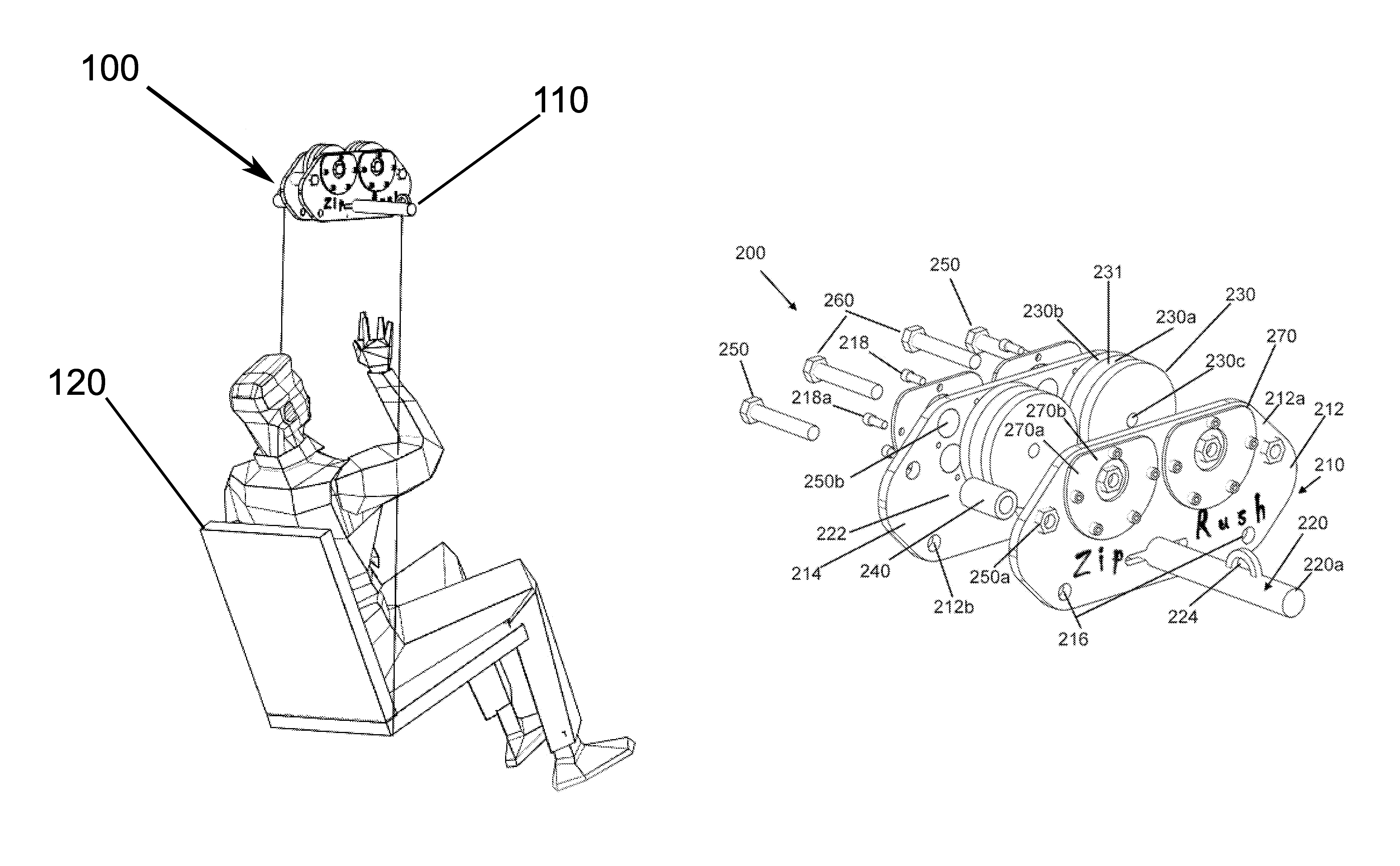
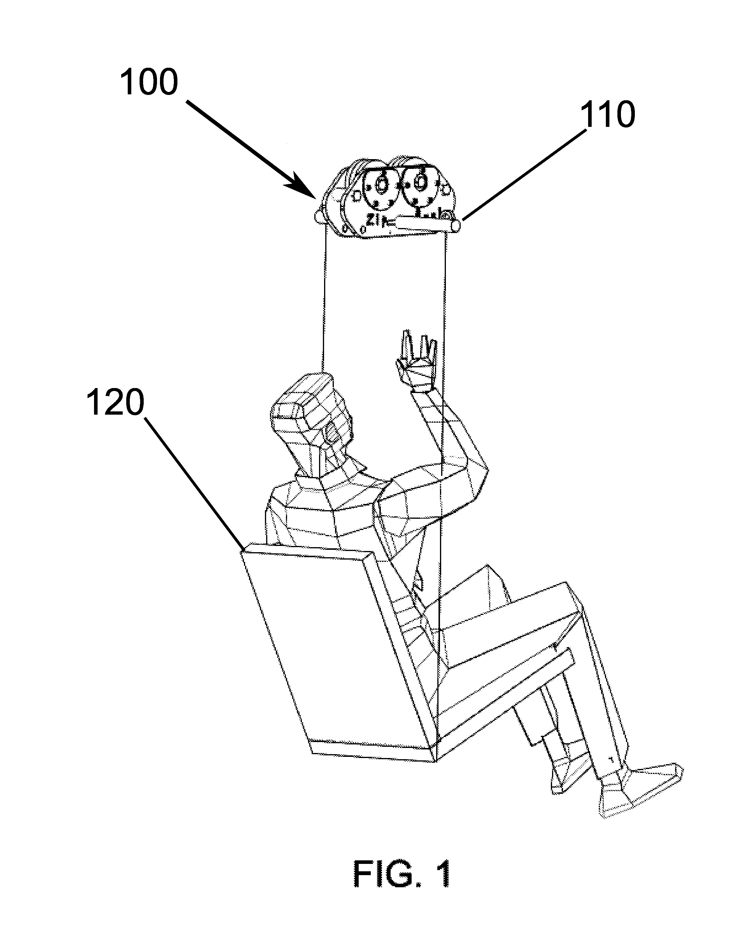
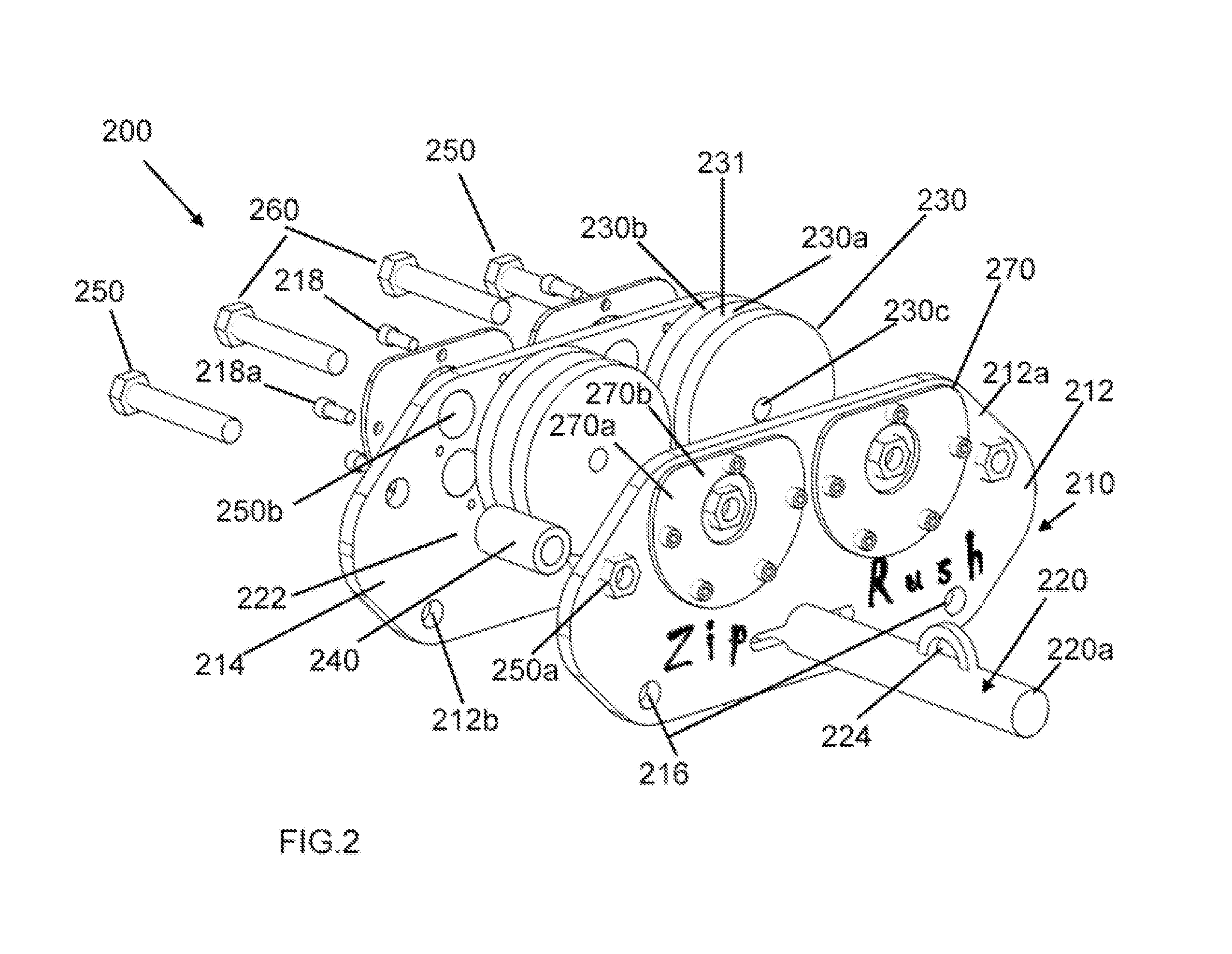
[0007]The high-speed magnetic trolley includes a body having a pair of planar trapezoidal shape parallel plates. The pair of parallel plates includes a plurality of harness coupling apertures to accommodate a chair harness, a climbing harness or a horizontal harness and a removable bar extended through a pair of aligned apertures disposed on the pair of parallel plates. The removable bar is utilized as a harness anchor when the trolley is ridden with the chair harness, wherein the removable bar is fitted with a harness attachment loop to act as an attachment point for the chair harness. The high-speed magnetic trolley also includes a plurality of wheels placed between the pair of parallel plates, the wheels each include a fitted track on a middle circumference portion of the wheels to accommodate the zip line cable. The thickness of one or more spacers define the air gap between the magnets and the aluminum wheel, the air gap between the one or more magnets and the wheels may be adjusted in the range of 1 / 32 of an inch to ¼ of an inch to provide more or less braking capability and reduce heat buildup.
[0009]It is an object of the present invention to provide a high-speed magnetic trolley that utilizes an eddy current brake that may reduce the speed of a person in a harness traveling on a relatively steep zip line cable, making it possible to reach a landing brake at a reasonable speed.
[0010]It is an object of the present invention to provide a high-speed magnetic trolley that becomes relatively easy to adjust the amount of braking force needed to reach a desired speed by taking off or adding more magnets without throwing one or more aluminum wheels out of balance.

Problems solved by technology

Many times a person on a zip line cable travelling over an area may go too fast and travel at dangerous speeds.
There are trolleys utilizing speed control devices but none that utilizes an eddy current device that also may be used with other types of harnesses used in combination with a zip line cable.

Method used


Image

  • High-speed magnetic trolley
  • High-speed magnetic trolley
  • High-speed magnetic trolley

Examples


Embodiment Construction

[0018]Various aspects of the illustrative embodiments will be described using terms commonly employed by those skilled in the art to convey the substance of their work to others skilled in the art. However, it will be apparent to those skilled in the art that the present invention may be practiced with only some of the described aspects. For purposes of explanation, specific numbers, materials and configurations are set forth in order to provide a thorough understanding of the illustrative embodiments. However, it will be apparent to one skilled in the art that the present invention may be practiced without the specific details. In other instances, well-known features are omitted or simplified in order not to obscure the illustrative embodiments.

[0019]Various operations will be described as multiple discrete operations, in turn, in a manner that is most helpful in understanding the present invention however the order of description should not be construed as to imply that these oper...


PUM


Abstract

A high-speed magnetic trolley that utilizes an eddy current brake that may reduce the speed of a person in a harness traveling on a relatively steep zip line cable, making it possible to reach a landing brake at a reasonable speed and becomes easy to adjust an amount of braking force needed to reach a desired speed by taking off or adding more magnets without throwing one or more aluminum wheels out of balance. The high-speed magnetic trolley produce an eddy current that generates an opposing magnetic field, which then resists rotation of one or more aluminum wheels providing braking force.

Description

[0001]This application claims priority to U.S. Provisional Application 61 / 658,259 filed on Jun. 11, 2012, the entire disclosure of which is incorporated by reference.BACKGROUND OF THE INVENTION[0002]1. Field of the Invention[0003]The present invention is a magnetic trolley. More specifically, the present invention is a high-speed magnetic trolley.[0004]2. Description of the Related Art[0005]Trolleys may be utilized with a harness to travel along a zip line cable over an area. Many times a person on a zip line cable travelling over an area may go too fast and travel at dangerous speeds. There are trolleys utilizing speed control devices but none that utilizes an eddy current device that also may be used with other types of harnesses used in combination with a zip line cable. The friction trolley device utilizes the rider's weight to counterbalance against a brake pad on a zip line cable as a user travels downward.BRIEF SUMMARY OF THE INVENTION[0006]The present invention is a magnetic...

Claims


Application Information

Patent Timeline
Patent Type & Authority Patents(United States)
IPC IPC(8): B61H9/02H02K49/04B60T13/74F16D63/00F16D121/20
CPCB61H9/02B60T13/748F16D63/002F16D63/008H02K49/046F16D2121/20
Inventor BERNIER, STEPHANE
Owner BERNIER STEPHANE
Learn More