Vehicle wheel changing method

a technology for changing wheels and vehicles, applied in the direction of tyre repairing, transportation and packaging, tyre parts, etc., can solve the problems of time-consuming and hazardous operation of wheel changing

Active Publication Date: 2016-02-02
TECH RESOURCES PTY LTD
View PDF4 Cites 13 Cited by
  • Summary
  • Abstract
  • Description
  • Claims
  • Application Information

AI Technical Summary

Problems solved by technology

The wheels of those trucks must be changed regularly as the tyres wear or sustain damage.
Wheel changing is a time consuming and hazardous operation.

Method used


Image

  • Vehicle wheel changing method
  • Vehicle wheel changing method
  • Vehicle wheel changing method

Examples


Embodiment Construction

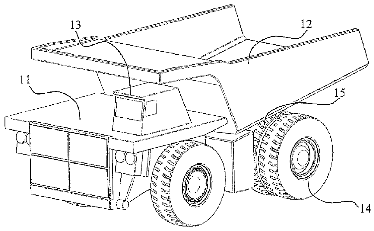
[0061]FIG. 1 illustrates a typical mine haul truck 11 having an ore carrier bin 12, a drivers cabin 13 and fitted with dual rear wheels 14 and single front wheels 15.

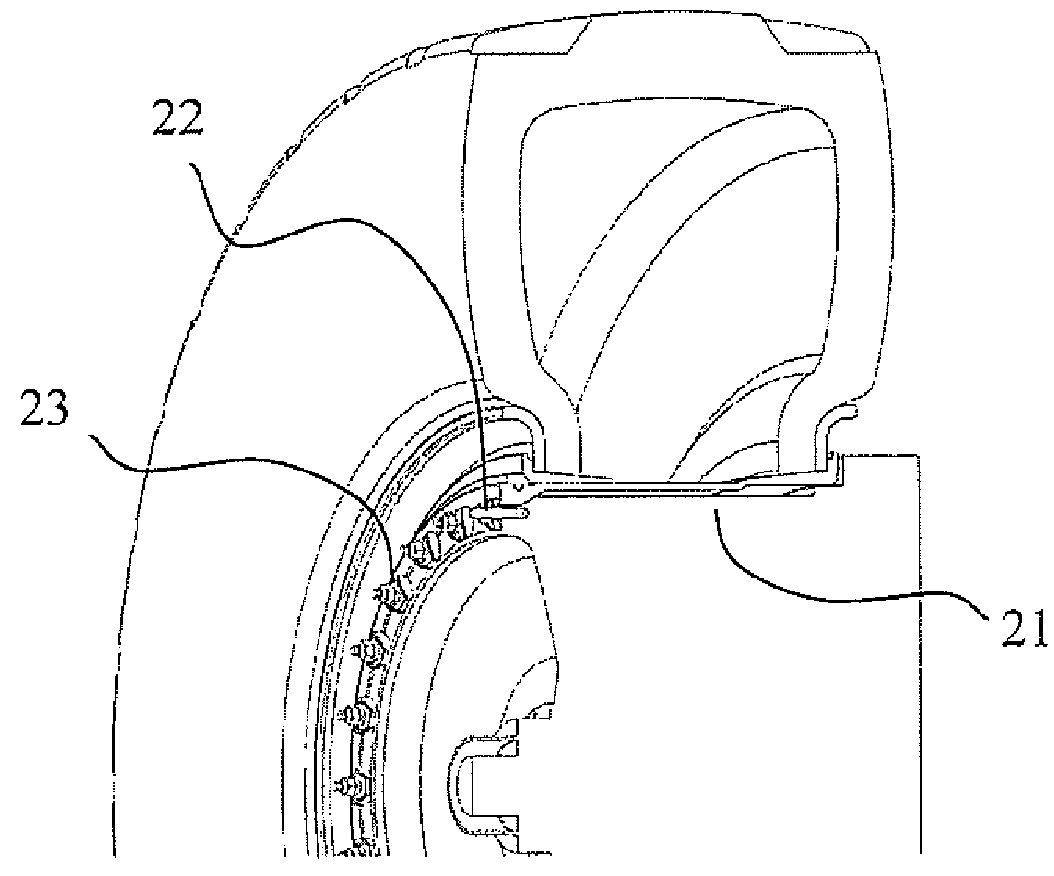
[0062]As shown in FIG. 2 the single front wheels of the haul truck are fastened on a tapered wheel hub 21 by fastening studs 22 and cleats 23.

[0063]As illustrated in FIG. 3 the dual rear wheels of the haul truck are held onto the tapered rear wheel hub 31 by studs 32 and cleats 33 with a spacer ring 34 extended between the inner and outer wheels of each pair. In order to replace the front or rear wheels of the haul truck the respective studs (22 or 32) and cleats (23 or 33) must be removed and replaced. In the case of the rear wheels the spacer ring 34 must also be removed after the outer wheel has been taken away and before the inner most wheel is removed.

[0064]During the removal and replacement of nuts and cleats the wheels must be held by a wheel handler to eliminate the potential for a wheel to fall. Conventionally ...


PUM

PropertyMeasurementUnit
pressureaaaaaaaaaa
timeaaaaaaaaaa
speedsaaaaaaaaaa

Abstract

A method for changing a vehicle wheel held to the vehicle by nuts and retainer cleats comprising: using a mobile robot for removal and replacement of the wheel nuts and retainer cleats in combination with the use of a mobile mechanical wheel handler to grip and remove the wheel and to bring a replacement wheel into position before replacement of the wheel nuts and cleats by the robot.

Description

CROSS-REFERENCE TO RELATED APPLICATIONS[0001]The present application is a U.S. National Phase filing of International Application No. PCT / AU2012 / 000020, filed on Jan. 12, 2012, designating the United States of America and claiming priority to Australia Patent Application No. 2011900085, filed Jan. 12, 2011, Australia Patent Application No. 2011900086, filed Jan. 12, 2011, and Australia Patent Application No. 2011900087, filed Jan. 12, 2011, and this application claims priority to and the benefit of the above-identified applications, which are incorporated by reference herein in their entireties.FIELD OF THE INVENTION[0002]This invention relates to techniques for changing wheels on wheeled vehicles, for example the wheels of large vehicles such as mining haul trucks.[0003]Open pit mines generally employ fleets of very large mining haul trucks. The wheels of those trucks must be changed regularly as the tyres wear or sustain damage. Wheel changing is a time consuming and hazardous ope...

Claims


Application Information

Patent Timeline
Patent Type & Authority Patents(United States)
IPC IPC(8): B60B29/00B60B23/10B60B23/04B60B25/20
CPCB60B29/007B60B23/04B60B23/10B60B25/20B60B29/00B60B29/008Y10S901/01Y10S901/09Y10T29/49492Y10T29/49815Y10T29/49822Y10T29/49826Y10T29/49947Y10T29/49948B60B30/00B60B31/00B62D65/12
Inventor CALVI, JOHN
Owner TECH RESOURCES PTY LTD
Why Eureka
Try Eureka