Infrared aided fuel emulsion

a fuel emulsion and infrared technology, applied in the direction of gaseous fuels, fuels, transportation and packaging, etc., can solve the problems of high interfacial tension, unstable emulsions, and difficulty in making a useful emulsion of hydrocarbon fuels, so as to reduce specific fuel consumption rate and emissions, improve performance, and cost-effective

Active Publication Date: 2016-02-02
ALDI FAR IR PROD INC
View PDF9 Cites 7 Cited by
  • Summary
  • Abstract
  • Description
  • Claims
  • Application Information

AI Technical Summary

Problems solved by technology

For examples, water-in-hydrocarbon emulsions have been extensively studied and shown some success in reducing targeted emissions from diesel engines, but unfortunately not without facing serious technical problems due to the stability of emulsions and the pollutants produced by the burning of emulsifying agent.
In spite of the theoretical potential of emulsified systems, aforementioned problems casted a shadow over the feasibility of commercial applications of such techniques.
Nonetheless, emulsions are unstable and, over time, tend to revert to the stable state of the phases comprising the emulsion.
In practical applications, the difficulty in making a useful emulsion of hydrocarbon fuel is on its high interfacial tension with the dispersed phase.
Furthermore, increasing temperature of the fuel, through fuel delivery system of a combustion device, may accelerate destabilization.
However, these additives are expensive and may add unwanted pollutants to the emissions during combustion, which would be better off to avoid, if possible.
Accordingly, one main challenge remains in the industry is to develop a stable and sustainable emulsion system without the need for relatively large amount of stabilizing agents.
As described above, the prior art failed to teach the use of IR-excitation in the making of fuel emulsions to improve fuel efficiency of the emulsified fuel in a combustion device for increased performance with reduced specific fuel consumption rate and emissions.

Method used


Image

  • Infrared aided fuel emulsion

Examples


Embodiment Construction

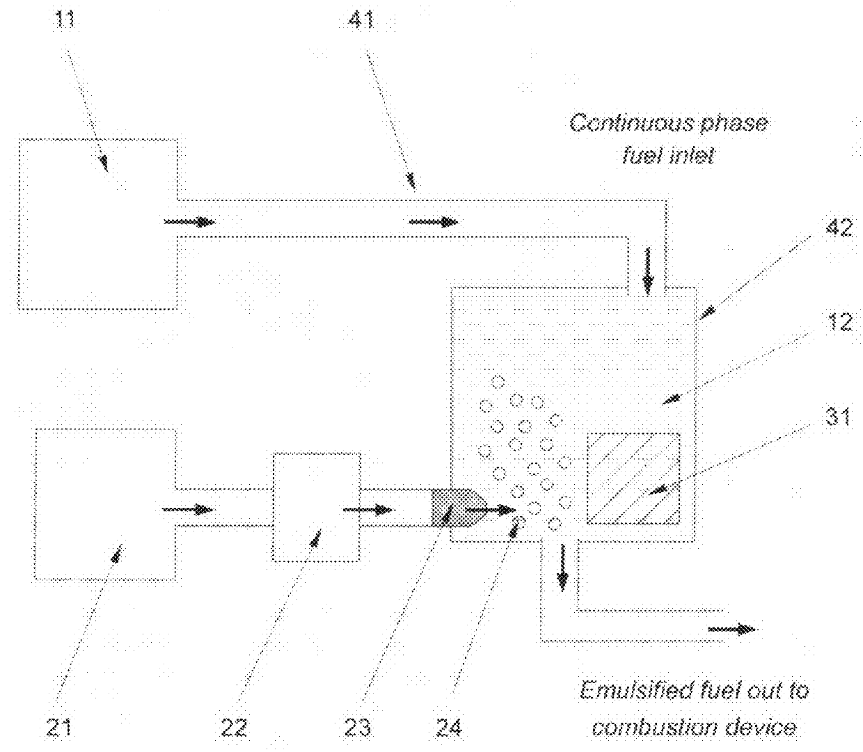
[0021]FIG. 1 shows one embodiment of the present invention with the infrared radiation source 31 being disposed in the continuous phase fuel 12 in a mixing chamber 42. The continuous phase fuel 12 is provided from a supply means 11 through a delivery means 41. The fuel supply means 11 may be a tank, equipped with a fuel pump, and the delivery means 41 a fuel line. The continuous phase fuel may be selected from fossil fuels, biofuels, alcohol fuels, vegetable oils, or any combustible liquid fuels.

[0022]The dispersed phase component supply means 21 may be, but not limited to, a storing means such as cylinder or tank that stores and supplies said dispersed phase component, which may be natural gas, oxygen, hydrogen, nitrogen, carbon monoxide, methane, propane, butane, any petroleum gas, hydrogen peroxide, or water. The dispersed phase component supply means 21 may further be a complicated production-on-demand device, such as water-electrolysis for hydrogen generation in the application...


PUM

PropertyMeasurementUnit
wavelengthsaaaaaaaaaa
wavelength spectrumaaaaaaaaaa

Abstract

This invention relates to a system and a method for generating emulsified fuels for improved fuel efficiency of combustion devices with reduced specific fuel consumption rate and emissions, comprising at least a continuous phase fuel, a dispersed phase component, and an infrared radiation source whose infrared radiation spans at least a portion of 3-16 micrometers wavelength spectrum. In said system the continuous phase fuel and / or dispersed phase component are exposed to said infrared before or during emulsification. The continuous phase fuel may be selected from fossil fuels, biofuels, alcohol fuels, vegetable oils, or any combustible liquid fuels, while the dispersed phase component may be oxygen, hydrogen, nitrogen, carbon monoxide, methane, propane, butane, any petroleum gas, hydrogen peroxide, or water. The emulsified fuels can be used in combustion devices such as internal combustion engines, boilers, burners, or gas turbines.

Description

BACKGROUND[0001]1. Field of Invention[0002]This invention relates to a system and a method for generating emulsified fuels for improved fuel efficiency in a combustion device to enhance its performance with reduced specific fuel consumption rate and emissions, comprising at least a continuous phase fuel, a dispersed phase component, and an infrared radiation source that spans at least a portion of 3-16 μm (micrometers) wavelength spectrum. In said system and method the continuous phase fuel and / or dispersed phase component are exposed to said infrared before or during emulsification process. The continuous phase fuel may be selected from fossil fuels, biofuels, alcohol fuels, vegetable oils, or any combustible liquid fuels, while the dispersed phase component may be oxygen, hydrogen, nitrogen, carbon monoxide, methane, propane, butane, any other petroleum gas, hydrogen peroxide, or water. Such emulsified fuels can be used in combustion devices such as internal combustion engines, bo...

Claims


Application Information

Patent Timeline
Patent Type & Authority Patents(United States)
IPC IPC(8): C10L1/32B01F3/08B01F13/00C10L3/06C10L3/00B01J19/08
CPCC10L3/00B01F3/0815B01F13/001C10L1/32C10L3/06B01F23/411B01F33/055B01F23/232B01F25/30C10L1/10C10L2200/0259C10L2250/08C10L2270/02C10L2290/14C10L2290/24C10L2290/36
Inventor WEY, ALBERT, CHIN-TANG
Owner ALDI FAR IR PROD INC
Why Eureka
Try Eureka