Power generator and power generating system

a power generator and power generating system technology, applied in the direction of dynamo-electric components, magnetic circuit shapes/forms/construction, dynamo-electric machines, etc., can solve the problems of increasing the number of processes for fixing the power generator to the duct, the difficulty of removing the power generator from the duct, so as to fix the power generator and achieve the effect of easy and stable removal process,

Active Publication Date: 2016-02-02
MITSUMI ELECTRIC CO LTD
View PDF16 Cites 8 Cited by
  • Summary
  • Abstract
  • Description
  • Claims
  • Application Information

AI Technical Summary

Benefits of technology

[0044]According to the present invention, it is possible to fixedly attach the power generator in an easy and stable way and make the process for removing the power generator from the vibrating body easy without any difficulties.

Problems solved by technology

Further, the number of processes for fixedly attaching the power generator to the duct increases because it is necessary to screw the screws for the fixation.
Furthermore, once the power generator is fixedly attached to the duct by such attachment, processes for removing the power generator from the duct become difficult because it is necessary to loosen the screws.
Further, once the power generator is fixedly attached to the duct by using the adhesive agent, it is extremely difficult to remove the power generator from the duct.

Method used


Image

  • Power generator and power generating system
  • Power generator and power generating system
  • Power generator and power generating system

Examples


first embodiment

[0065]Description will be first given to a power generator 100 according to the present invention.

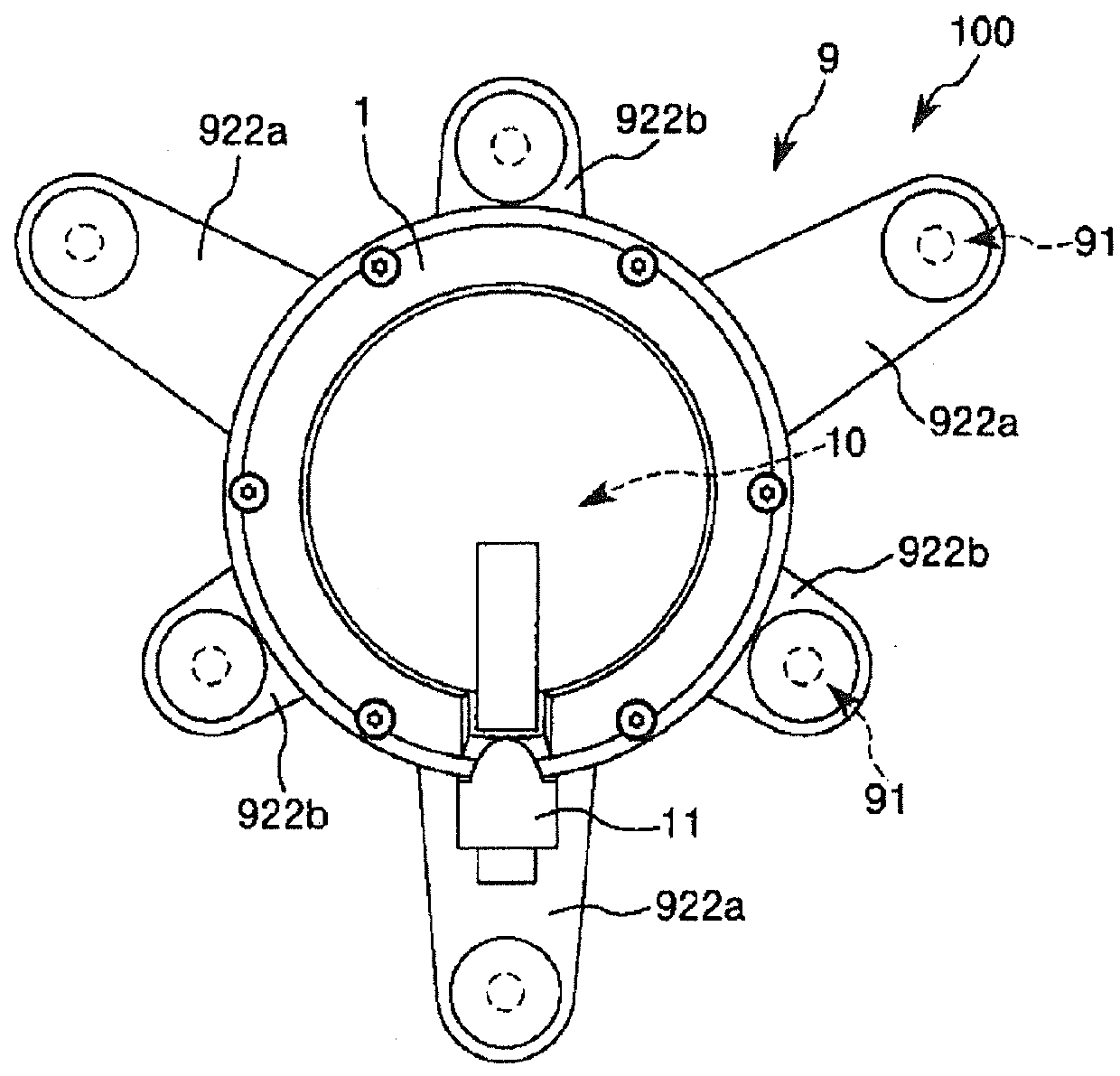
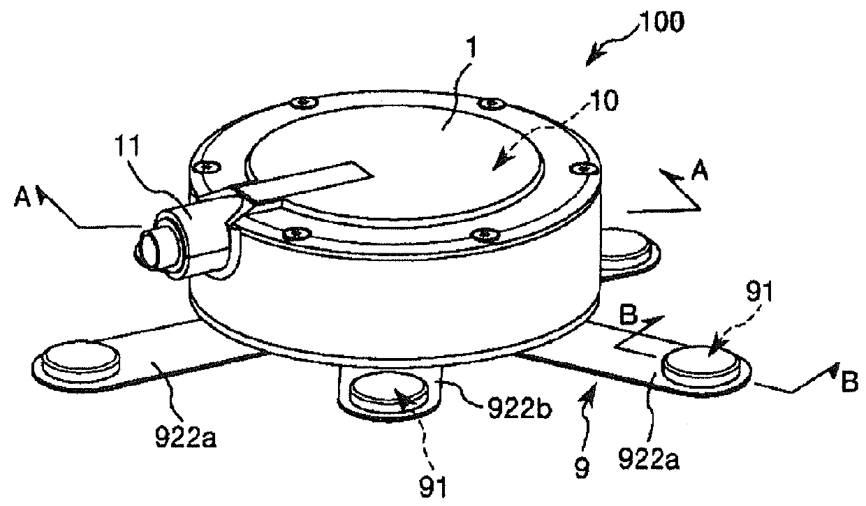
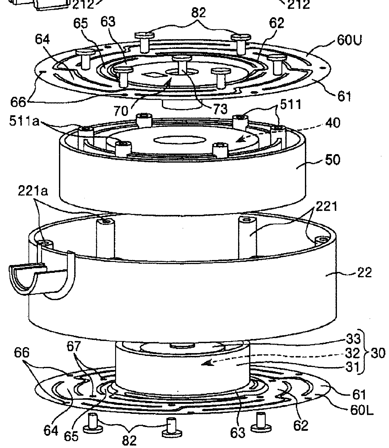
[0066]FIG. 1 is a perspective view showing the power generator 100 according to the first embodiment of the present invention. FIG. 2 is a planar view showing the power generator 100 shown in FIG. 1. FIG. 3 is an exploded perspective view showing a main unit of the power generator shown in FIG. 1. FIG. 4 is a cross-sectional view taken along with an A-A line shown in FIG. 1 (a vertical cross-sectional view showing the main unit shown in FIG. 3). FIG. 5 is a planar view showing a leaf spring included in the main unit shown in FIG. 3. FIG. 6 is an exploded perspective view showing a mounting mechanism of the power generator shown in FIG. 1. FIG. 7 is a cross-sectional view taken along with a B-B line shown in FIG. 1. FIG. 8 is a perspective view showing the power generator 100 shown in FIG. 1, which shows a state for use (attached state). FIG. 9 is an enlarged side view showing the power ...

second embodiment

[0167]Next, description will be given to a power generator 100 according to the present invention.

[0168]FIG. 11 is a perspective view showing the power generator 100 according to the second embodiment of the present invention. FIG. 12 is a perspective view showing the power generator 100 shown in FIG. 11, which shows a state for use (attached state). Hereinafter, an upper side in each of FIGS. 11 and 12 is referred to as “upper” or “upper side” and a lower side in each of FIGS. 11 and 12 is referred to as “lower” or “lower side”.

[0169]Hereinafter, the power generator 100 according to the second embodiment will be described by placing emphasis on the points differing from the power generator 100 according to the first embodiment, with the same matters omitted from description. The power generator 100 according to the second embodiment has the same structure as the first embodiment except that the structure of the attachment 9 is modified.

[0170]The attachment 9 according to the second...

third embodiment

[0179]Next, description will be given to a power generator 100 according to the present invention.

[0180]FIG. 14 is a perspective view (taken from a lower side) showing the power generator 100 according to the third embodiment of the present invention. FIG. 15 is a view showing a structure of an attachment 9 of the power generator 100 shown in FIG. 14 (FIG. 15a is a vertical cross-sectional view and FIG. 15b is an exploded perspective view). Hereinafter, an upper side in each of FIGS. 14 and 15 is referred to as “upper” or “upper side” and a lower side in each of FIGS. 14 and 15 is referred to as “lower” or “lower side”.

[0181]Hereinafter, the power generator 100 according to the third embodiment will be described by placing emphasis on the points differing from the power generator 100 according to the first embodiment, with the same matters omitted from description. The power generator 100 according to the third embodiment has the same structure as the first embodiment except that th...


PUM


Abstract

A power generator 100 of the present invention is configured to be used in a state that the power generator 100 is fixedly attached to a vibrating body formed of a magnetic material. The power generator 100 includes a main unit 1 having a power generating unit 10 configured to generate electric power by utilizing vibration and a base 23 having one surface on which the power generating unit 10 is supported and another surface 230 opposed to the one surface; and at least one permanent magnet 911 disposed on the side of the other surface 230 of the base 23 in a state that the permanent magnet 911 can be displaced or deformed in a thickness direction of the base 23. When the main unit 1 is fixedly attached to the vibrating body through an attachment 9 including the permanent magnet 911, the main unit 1 is configured to generate the electric power by utilizing vibration of the vibrating body.

Description

CROSS REFERENCE TO RELATED APPLICATION[0001]This application claims priority to Japanese patent application no. 2012-238012, filed Oct. 29, 2012, herein incorporated by reference.BACKGROUND OF THE INVENTION[0002]1. Field of the Invention[0003]The present invention relates to a power generator and a power generating system.[0004]2. Description of the Prior Art[0005]Recently, various power generators to be used in a state that the power generators are fixedly attached to ducts are developed in order to achieve space-saving and efficient power generation. Such power generators can generate electric power by utilizing vibration of the ducts. For example, see a patent document 1 (JP 2011-172352A). The patent document 1 discloses a power generator to be used in a state that the power generator is fixedly attached to a duct by using attachments. Each of the attachments can fixedly attach the power generator on the duct by using screws.[0006]In such method using the attachments disclosed in...

Claims


Application Information

Patent Timeline
Patent Type & Authority Patents(United States)
IPC IPC(8): H02K35/04H02K7/18H02K5/26H02K35/00H02K35/02H02K1/06
CPCH02K35/00H02K5/26H02K7/1876
Inventor FURUKAWA, KENICHIYAMADA, KENSUKE
Owner MITSUMI ELECTRIC CO LTD
Why Eureka
Try Eureka